External weight for golf club head

a golf club and external weight technology, applied in the field of golf club head manufacture, can solve the problems of increasing dispersion, reducing distance, and reducing distance, and achieve the effect of effective adjustment of center of gravity and moment of inertia

Active Publication Date: 2013-04-09
TOPGOLF CALLAWAY BRANDS CORP
View PDF91 Cites 388 Cited by
  • Summary
  • Abstract
  • Description
  • Claims
  • Application Information

AI Technical Summary

Problems solved by technology

Although this approach was effective in increasing the moments of inertia of the golf club heads, it also resulted in the center of gravity of the golf club head being positioned substantially rearward from the front face of the golf club head.
As the center of gravity is positioned further rearward from the front face, deleterious effects result for shots struck off-center from the sweet spot of the golf club head.
Increased gear effect is the main cause of the deleterious effects.
For heel-ward or toe-ward off-center hits, the increased gear effect can cause increased side-spin, which increases dispersion, reduces distance and reduces robustness of ball flight.
For off-center hits above the sweet spot, the increased gear effect causes reduced backspin, which can cause an undesirable trajectory having insufficient carry length or time of flight, which in turn can result in reduced distance and reduced robustness.
In addition, the same conventional golf club head designs are limited with regard to the maximum face area, both physical and practical limitations.
The physical limitation is due to the golf club head having insufficient mass to both increase the length and width of the golf club head and also to increase the face size without exceeding the upper range of the preferred total golf club head mass.
The practical limitation is that as the face size is increased, hit locations in certain regions around the face perimeter will yield an unsatisfactory ball flight due to the aforementioned deleterious effects, which are accentuated for larger faces.
Thus the incremental face area gained by increasing face size will be subject to more extreme deleterious effects.
This limits the practical length of the club, because probable hit distribution across the surface of the face broadens as the club length increases.
Further, conventional head designs having a center of gravity positioned substantially rearward from the face are subject to significant dynamic loft effects, which can be undesirable.
This is opposite of what is desired as higher head speeds generally require less loft, otherwise excess backspin will be generated, which negatively affects trajectory and performance.

Method used


Image

  • External weight for golf club head
  • External weight for golf club head
  • External weight for golf club head

Examples


Embodiment Construction

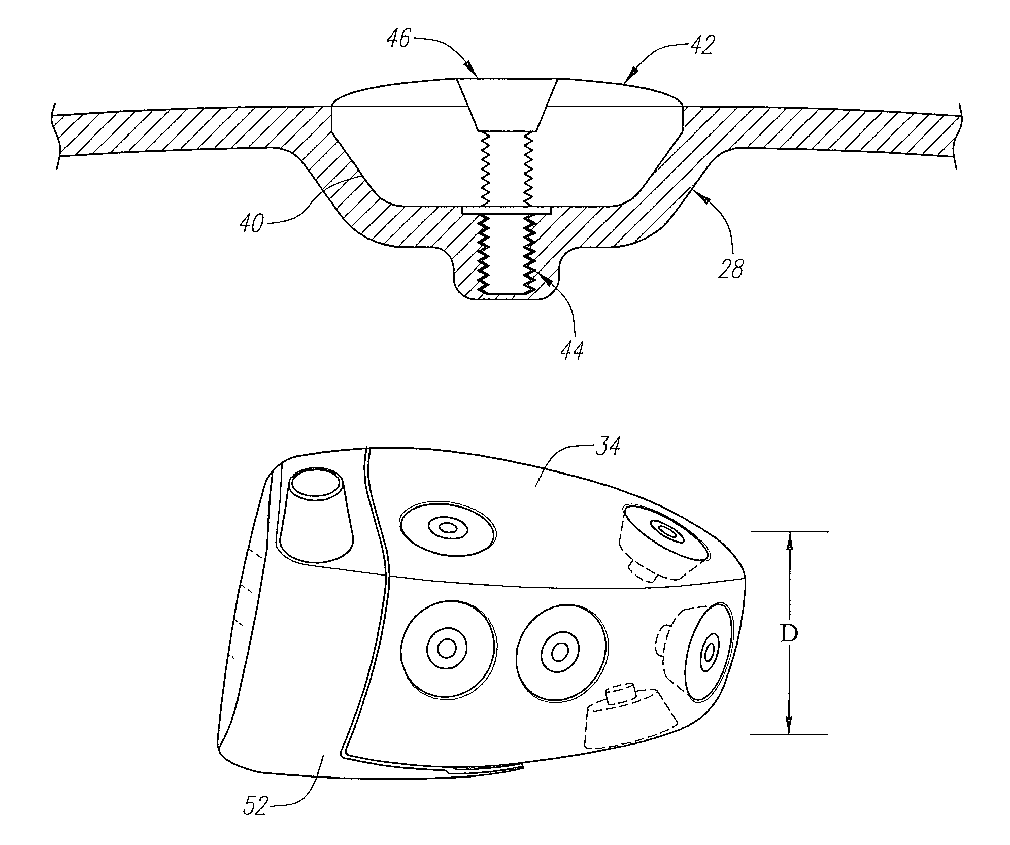
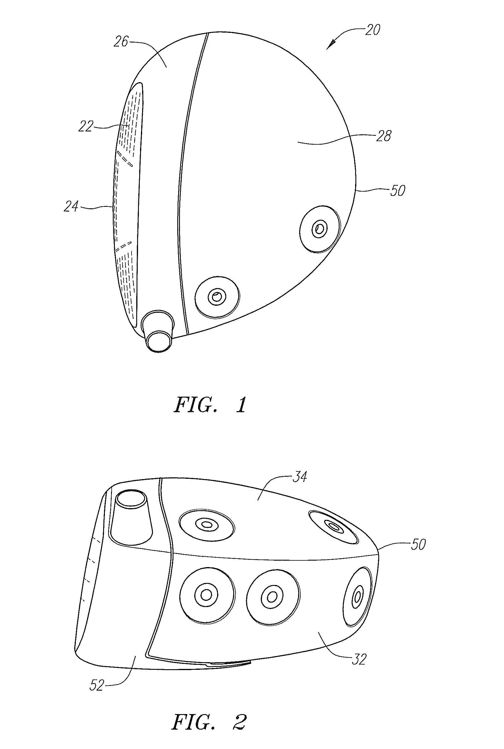
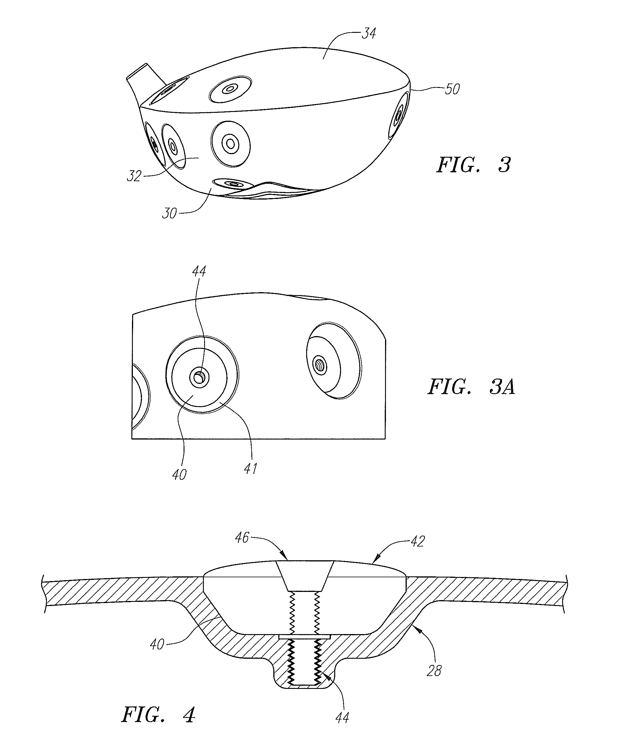
[0032]As shown in FIGS. 1-9, the present invention comprises a golf club head 20 which has a face component 22 comprising a front wall 24 and a return portion 26. The face component 22 is composed of a non-metallic material. The golf club head 20 further comprises an aft body 28 connected to the face component 22. The aft-body 28 comprises a sole portion 30, a ribbon portion 32 and a crown portion 34. The aft-body 28 is composed of a non-metallic material. The golf club head 20 also has a back portion 50, a heel portion, 52 and a toe portion 54.

[0033]A plurality of recessed cavities 40 are located on the aft-body. A weight 42 is disposed within the recessed cavities 40. In a preferred embodiment, a weight 42 is disposed in each recessed cavity 40. In an alternative embodiment, only those recessed cavities 40 are engaged with a weight 42 as required to effectively adjust the center of gravity and moment of inertia for the individual golfer. The weight 42 preferably ranges in mass bet...


PUM


Abstract

The present invention relates to a golf club head with external weights that allows for weight modification after the manufacturing process. The golf club head comprises a face component and an aft-body. A plurality of recessed cavities are located on the aft-body. A weight component is disposed within the recessed cavities. A timesert is located at the bottom center of each of the recessed cavities. The timesert is comolded to the aft-body. The weight component is fastened to the timesert by use of a bolt. The recessed cavities are preferably circular in shape.

Description

CROSS REFERENCES TO RELATED APPLICATIONS[0001]The Present Application claims priority to U.S. Provisional Patent Application No. 61 / 286971, filed on Dec. 16, 2009, which is hereby incorporated by reference in its entirety.STATEMENT REGARDING FEDERALLY SPONSORED RESEARCH OR DEVELOPMENT[0002]Not ApplicableBACKGROUND OF THE INVENTION[0003]1. Field of the Invention[0004]The present invention relates to the manufacture of golf club heads. Particularly to the manufacture of a golf club head with an improved center of gravity and moment of inertia.[0005]2. Description of the Related Art[0006]As driver golf club heads have increased in volume (>300 cubic centimeters) their moments of inertia have also increased, providing greater forgiveness for off-center hits. The conventional method for enlargement of golf club heads was to maximize the spatial distribution of mass in all three orthogonal orientations. Although this approach was effective in increasing the moments of inertia of the go...

Claims


Application Information

Patent Timeline
Patent Type & Authority Patents(United States)
IPC IPC(8): A63B53/04
CPCA63B53/0466A63B2053/0491A63B2053/0437A63B2209/02A63B2053/0433A63B2209/00A63B53/0437A63B53/0433A63B60/02A63B53/04
Inventor PERALTA, MARTINHOCKNELL, ALAN
Owner TOPGOLF CALLAWAY BRANDS CORP
Why Eureka
Try Eureka