Bearing mechanism for a transverse leaf spring, mountable in the area of a vehicle axle

a technology of bearing mechanism and vehicle axle, which is applied in the direction of springs, plant products, transportation and packaging, etc., can solve the problems of increasing the need for construction space and production costs, increasing the need for construction space and cost, and achieving low construction space requirements. , the effect of easy and cost-effective production

Inactive Publication Date: 2013-05-21
ZF FRIEDRICHSHAFEN AG
View PDF26 Cites 5 Cited by
  • Summary
  • Abstract
  • Description
  • Claims
  • Application Information

AI Technical Summary

Benefits of technology

[0009]Therefore, the problem addressed by the present invention is that of providing a bearing mechanism of a transverse leaf spring that can be mounted in the region of a vehicle axle of a vehicle, which can be produced easily and cost effectively, is characterized by a low construction space requirement, and in the region of which movement of a transverse leaf spring is ensured to an extent necessary for the operation.

Problems solved by technology

Disadvantageously, the above-described leaf spring suspension is characterized by a need for a large amount of construction space and by production complexity that is greater than desired, in the region of the central bearings in particular, since the layer elements of the insertion devices, which can be bolted together, must be solid design and provided with a thread impression in order to receive the bolting regions and transmit the pretensioning forces.
In addition, the central bearings comprise a large number of parts, thereby further increasing the need for construction space and the production costs.
A disadvantage thereof is that the bearing mechanism comprises rigid bearing elements which impede movement of the transverse leaf spring in the loaded bearing region and thereby impair an overall behavior of the spring system and the overall spring action to an undesired extent.

Method used


Image

  • Bearing mechanism for a transverse leaf spring, mountable in the area of a vehicle axle
  • Bearing mechanism for a transverse leaf spring, mountable in the area of a vehicle axle
  • Bearing mechanism for a transverse leaf spring, mountable in the area of a vehicle axle

Examples


Embodiment Construction

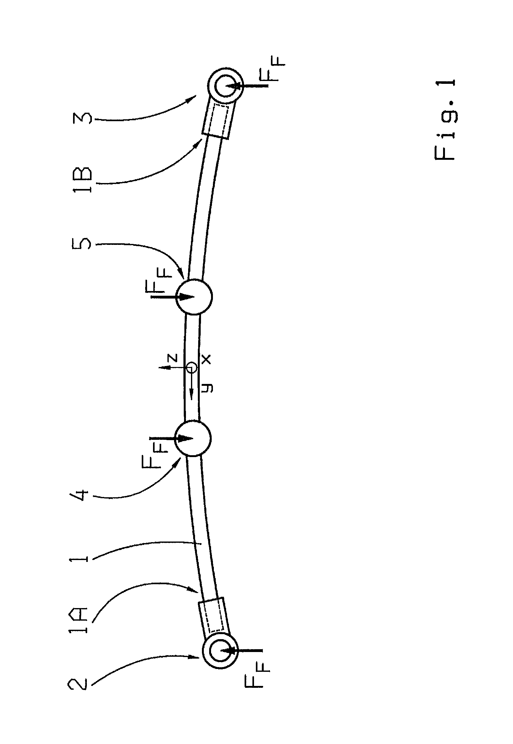
[0052]FIG. 1 shows a highly schematic representation of a transverse leaf spring 1 that can be mounted in the region of a vehicle axle of a vehicle. The transverse leaf spring 1 is supported at the end regions 1A, 1B thereof facing toward wheels of the vehicle axle, in outer bearings 2, 3 or guide bearings, designed here as so-called bearing shoes, and connected to wheel carriers of the vehicle axle.

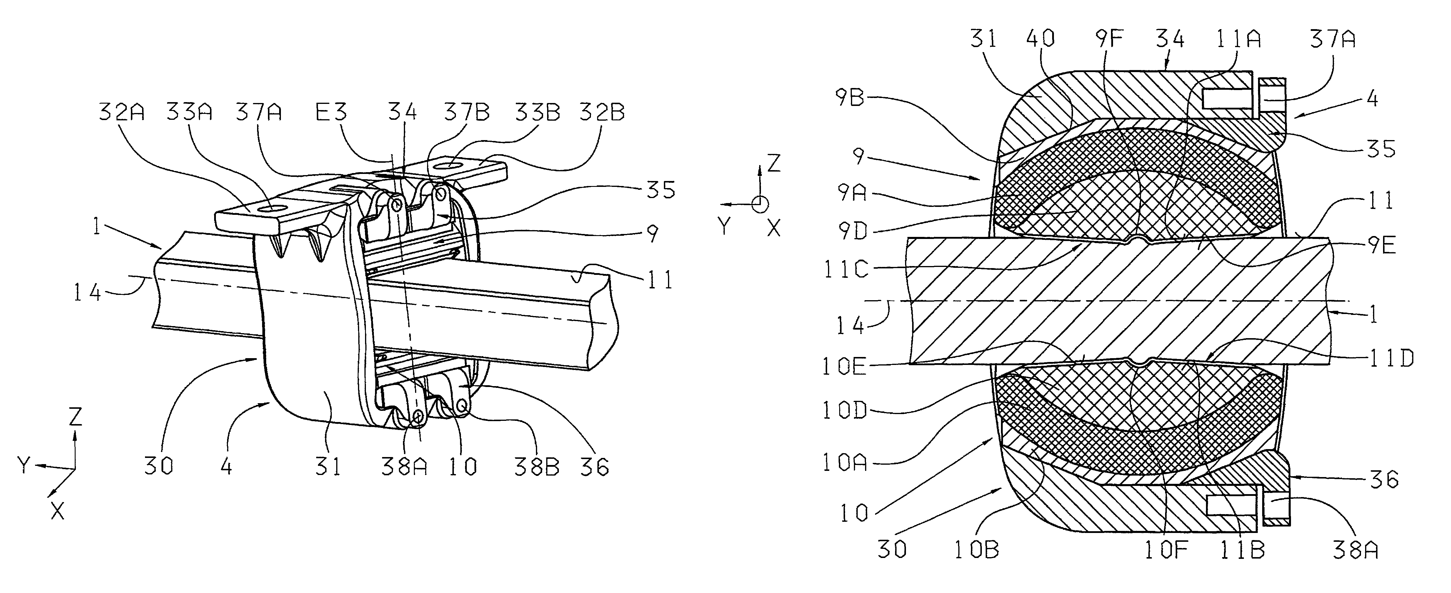
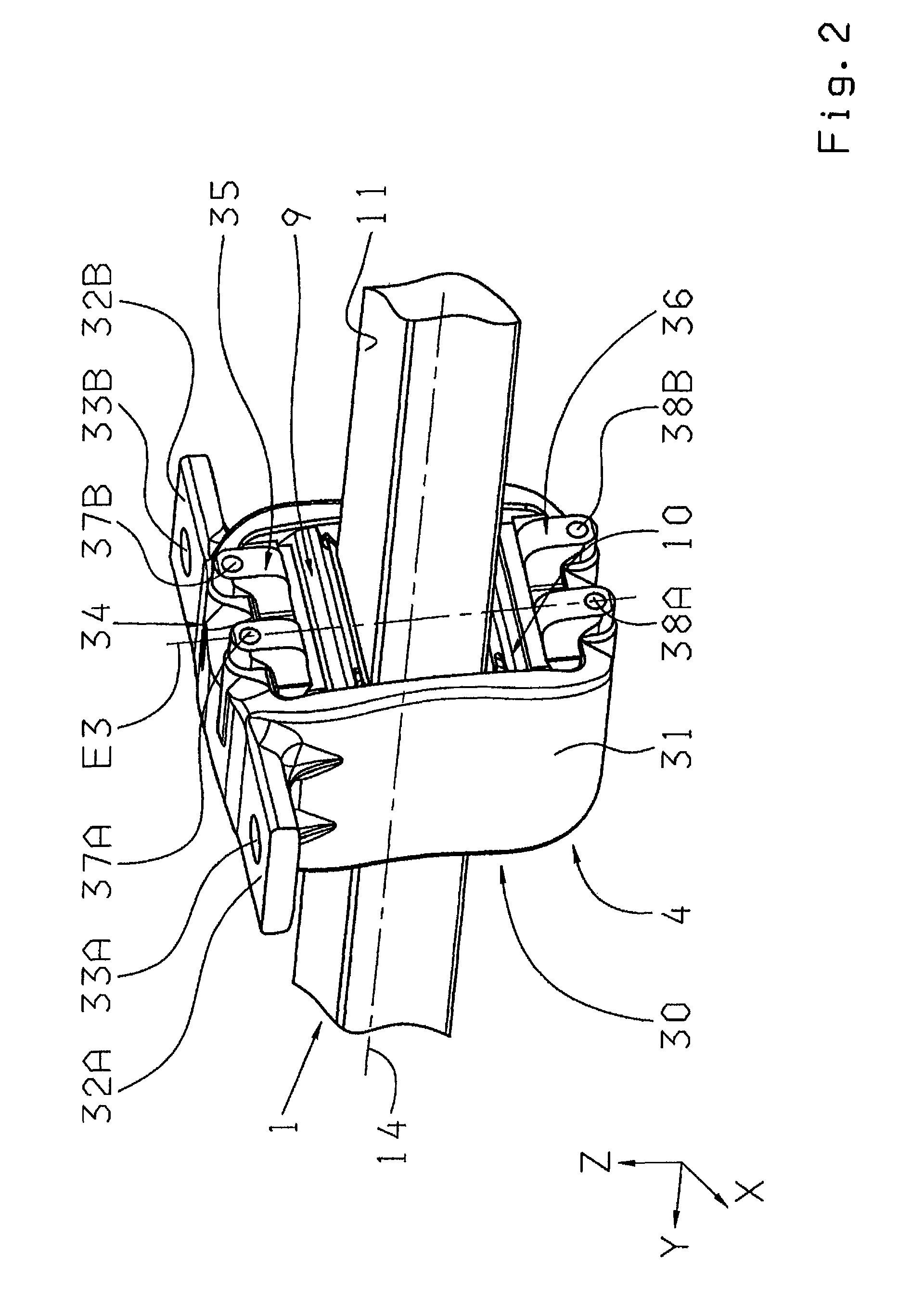
[0053]The transverse leaf spring 1 in the center region thereof is effectively connected, directly to a vehicle chassis or to an auxiliary frame connected in turn the vehicle chassis and supported thereon via bearing mechanisms 4, 5 acting as a central bearing. The bearing mechanisms 4 and 5 are disposed symmetrically about the center of the transverse leaf spring 1 and connect the mechanisms to the vehicle chassis in a manner described below, where rotations of the transverse leaf spring 1 in the region of the bearing mechanisms 4 and 5 are possible to the required extent during unidire...


PUM

PropertyMeasurementUnit
stiffnessesaaaaaaaaaa
coefficient of frictionaaaaaaaaaa
pretensioning forceaaaaaaaaaa

Abstract

A bearing mechanism for a transverse leaf spring that can be mounted near an axle of a vehicle. The bearing mechanism has an outer bearing shell device and insertion devices which have at least some regions encompassed by the outer bearing shell device. Each of the insertion devices comprise at least two layer elements which have different stiffness. In the assembled state, the insertion devices are each disposed between the outer bearing shell device and the transverse leaf spring. The outer bearing shell device comprises a one-piece bearing ring element, and the insertion devices can be operatively connected, at least in a force locking manner, to the bearing ring element and the transverse leaf spring, via tensioning elements.

Description

[0001]This application is a national stage completition of PCT / EP2010 / 061676 filed Aug. 11, 2010 which claims priority from German Application Serial No. 10 2009 028 899.6 filed Aug. 26, 2009.FIELD OF THE INVENTION[0002]The invention relates to a bearing mechanism for a transverse leaf spring that can be mounted in the region of a vehicle axle of a vehicle.BACKGROUND OF THE INVENTION[0003]A wheel suspension for a motor vehicle having a transverse leaf spring disposed transverse to the motor vehicle is known from the document EP 1 645 445 B1. The transverse leaf spring comprises a central region and two opposing end regions, where the transverse leaf spring is connected in the central region to a vehicle chassis via two central bearings, and in the end regions it is operatively connected to wheel carriers via end bearings.[0004]The central bearings are each formed having two outer bearing shells that can be connected together and having insertion devices encompassed by the outer bear...

Claims


Application Information

Patent Timeline
Patent Type & Authority Patents(United States)
IPC IPC(8): B60G11/00
CPCB60G11/08B60G11/10B60G11/12F16F1/3683B60G2202/114B60G2204/121B60G2204/41B60G2204/4104B60G2204/43B60G2204/4302B60G2204/44B60G2204/82B60G2204/8302B60G2206/428B60G2206/7101B60G2206/73
Inventor FRUHMANN, GABRIELEWAGNER, VOLKERHEIMANN, JENS
Owner ZF FRIEDRICHSHAFEN AG
Why Eureka
Try Eureka