Lamp module for a glare-free motor vehicle high beam

a technology for motor vehicles and headlamps, applied in fixed installations, lighting and heating devices, lighting support devices, etc., can solve the problems of unfavorable conditions for the generation of good intermediate images, undesired color fringes of light-retracting secondary lenses, etc., to reduce blinding or brighten, eliminate chromatic aberrations of refracting lenses, and easy and cost-effective

Inactive Publication Date: 2014-08-12
AUTOMOTIVE LIGHTING REUTLINGEN GMBH
View PDF11 Cites 4 Cited by
  • Summary
  • Abstract
  • Description
  • Claims
  • Application Information

AI Technical Summary

Benefits of technology

[0015]The horizontal configuration of the light-emitting surfaces is transferred, with the invention, to the configuration of its images in the light distribution in front of the lamp module on the street. By tire horizontal configuration of the light-emitting surfaces, it is possible (in conjunction with the individual controllability of the luminous flux via the respective light-emitting surfaces) to dim partial regions of the high-beam-light distribution in the horizontal plane (with a width depending on one of the numerous light-emitting surfaces) in a controlled manner to reduce the danger of blinding or brighten in a targeted manner to generate a “spotlight” type narrow strip of light. The partial regions vary in terms of their horizontal positions in the light distribution. In this respect, it is possible to distinguish partial regions that are more to the right, more to the left, or substantially in the center.
[0016]Because the mapping takes place by a reflector without generating an actual intermediate image, installation times are eliminated, which are necessary with systems functioning with an intermediate image for generating the intermediate image between a primary lens and a projection lens. The use of a reflector in place of a lens has the advantage that chromatic aberrations occurring with refracting lenses are eliminated. Furthermore, reflectors can be more easily and cost-effectively produced than lenses and do not cause any undesired diffusion as a result of “Fresnel effects.” On the other hand, reflectors have the disadvantage that with larger numbers of apertures, aperture failures occur. This also applies to refractive lenses, but, in this case, can be corrected with more lenses.
[0022]A partial high beam (composed of individual strips each of which is generated by a direct mapping, without generating an intermediate image, of a light source exhibiting different light-emitting surfaces) requires a constant width of the strip over the course of the length of the strip. The invention enables the generation of a partial high beam of this type having a significantly lower number of components in comparison with the prior art, which represents an advantage with respect to the cost expenditures, assembly and adjustment expenditures, and weight. Through the combining of numerous light-emitting surfaces in a reflector or a reflector chamber the coherent reflector surfaces of which are illuminated by luminous fluxes from numerous light-emitting surfaces, an extensive adjustment of the individual strips in relation to one another during the assembly is also eliminated. Numerous lamp modules can be combined with one another. In this case, an adjustment of the lamp module is provided.

Problems solved by technology

Due to the imprecisions in the positioning of the SMD-LEDs, unfavorable conditions for the generation of a good intermediate image exist, which primarily is to be distinguished by its homogeneity and sharply focused edges of its partial regions formed by individual LEDs.
Other problems arise with systems of this type in that the light-retracting secondary lenses inevitably generate undesired color fringes at “light / dark” borders.
Reflectors are also a fundamental possibility, but they are accompanied by other problems.

Method used


Image

  • Lamp module for a glare-free motor vehicle high beam
  • Lamp module for a glare-free motor vehicle high beam
  • Lamp module for a glare-free motor vehicle high beam

Examples


Embodiment Construction

[0035]Identical reference symbols in different figures indicate the same components or at least components having the same functions.

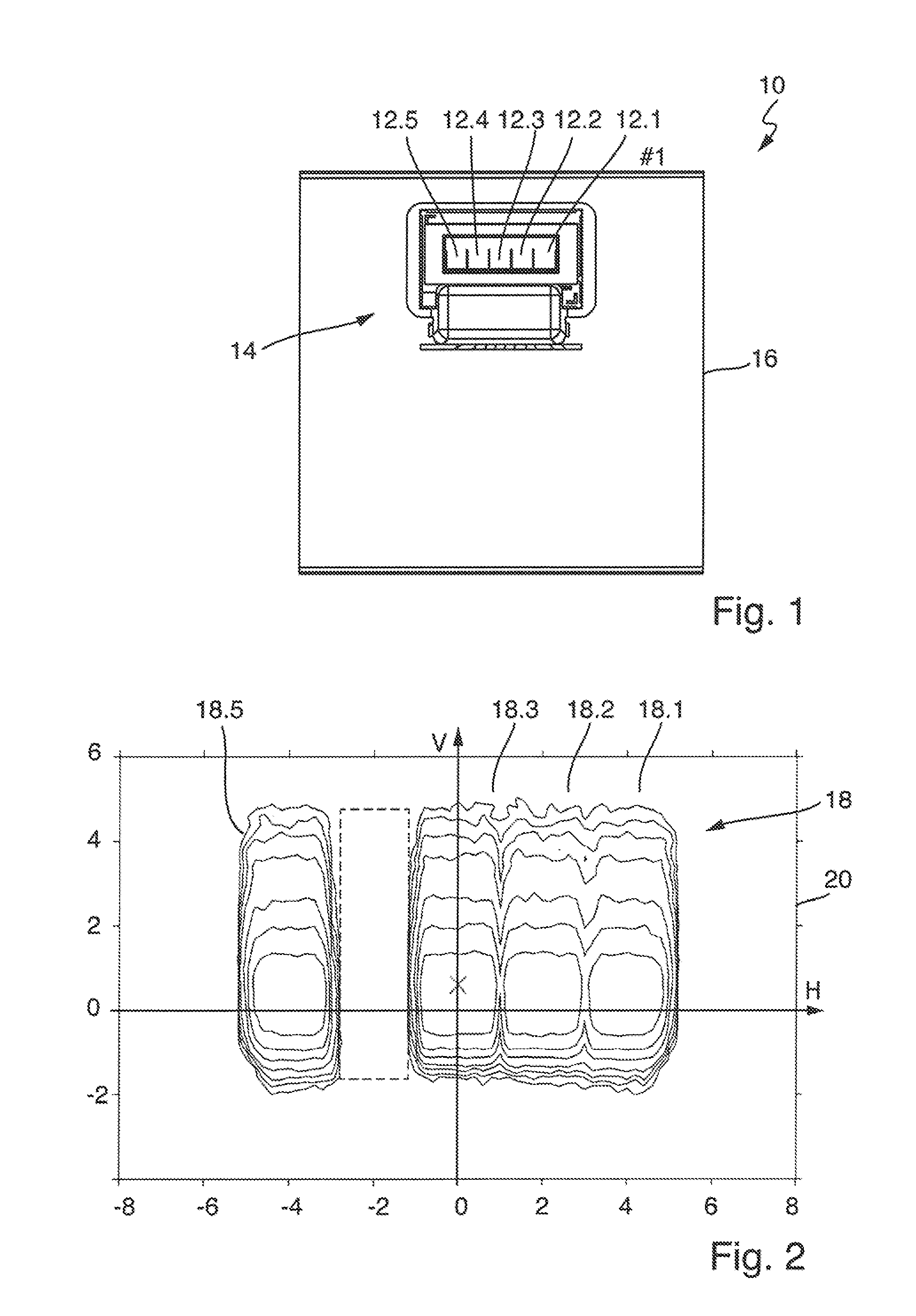
[0036]FIG. 1 shows a top view of a light source 10 having “n=5” light-emitting surfaces 12.1-12.5. It is understood that “N” can be any natural number greater than or equal to 1.

[0037]In an embodiment, each light-emitting surface belongs to one LED chip (LED=light-emitting diode). The LED chips are installed on a common interconnect device 14. The supply of electric energy and the control are obtained via the interconnect device.

[0038]The LEDs can be individually controlled as single units and / or in groups such that the luminous flux emitted from each light-emitting surface can be controlled individually. The controllability includes, thereby, in an embodiment, not only a switching between permanently “on” and permanently “off,” but also a control of the brightness, which, for example, can take place by an activation with a duty cycle having a signal f...


PUM


Abstract

A lamp module for a motor-vehicle headlamp. The lamp module comprises a light source defining at least one light-emitting surface that emits a luminous flux and defines a horizontally oriented longitudinal edge and at least one other edge running at a right angle thereto. A reflector maps the light-emitting surface without generating an actual intermediate image in front of the lamp module and defines at least two reflecting and strip-shaped facets longitudinal axes of which are more parallel rather than transversal to the longitudinal edge of the light-emitting surface and disposed at a spacing to the light source where the light-emitting surface is mapped with the same mapping scale in front of the lamp module such that the light-emitting surface is mapped with a longitudinal edge running horizontally and another edge running vertically.

Description

CROSS-REFERENCE TO RELATED APPLICATION[0001]This application is based upon and claims priority to German Patent Application 10 2012 202 290.2 filed on Feb. 15, 2012.BACKGROUND OF INVENTION[0002]1. Field of Invention[0003]The invention relates to a lamp module for a motor-vehicle headlamp having a light source exhibiting at least two light-emitting surfaces each of which emits a luminous flux that can be controlled individually.[0004]2. Description of Related Art[0005]A lamp module of this type is known from, for example, EP 2 306 074, and suitable for generating a glare-fee high beam for motor vehicles. A glare-free high beam is understood to be high-beam light distribution in which partial regions can be dimmed if there is someone located in these partial regions who could be blinded therefrom. This could be, for example, the driver of a preceding or oncoming vehicle. A lighting function of this type is referred to a “partial high beam.”[0006]The invention serves to, in particular,...

Claims


Application Information

Patent Timeline
Patent Type & Authority Patents(United States)
IPC IPC(8): F21V7/00F21S8/10F21W107/10
CPCF21S48/1159F21S48/1376F21S48/1352F21S48/1388F21S48/1747F21S48/328F21S41/147F21S41/285F21S41/321F21S41/336F21S41/36F21S41/663F21S41/365F21S45/48F21S41/153F21S41/337
Inventor BRENDLE, MATTHIAS
Owner AUTOMOTIVE LIGHTING REUTLINGEN GMBH
Why Eureka
Try Eureka