Leakage connection for a fuel injector

a technology of leakage connection and fuel injector, which is applied in the direction of fuel injection apparatus, cylinders, charge feed systems, etc., can solve the problems of large backflow of fuel from the fuel injector, large number of components, and large amount of components, and achieves easy and cost-effective production, facilitates secure sealing, and is easy to install

Inactive Publication Date: 2005-03-03
SIEMENS AG
View PDF19 Cites 5 Cited by
  • Summary
  • Abstract
  • Description
  • Claims
  • Application Information

AI Technical Summary

Benefits of technology

[0006] The object of this invention, therefore, is to provide a leakage connection for an injector, which is simple to install and can be produced easily and cost-effectively, and which facilitates a secure seal between the leakage connection and a leakage return line.

Problems solved by technology

Because of the high pressure, there is a greater backflow of fuel from the fuel injector particularly during the control process by the control valve.
This arrangement, however, is relatively expensive and incorporates a great many individual components.
This solution, however, likewise has a great many components and entails relatively high production and installation costs.

Method used


Image

  • Leakage connection for a fuel injector
  • Leakage connection for a fuel injector
  • Leakage connection for a fuel injector

Examples


Embodiment Construction

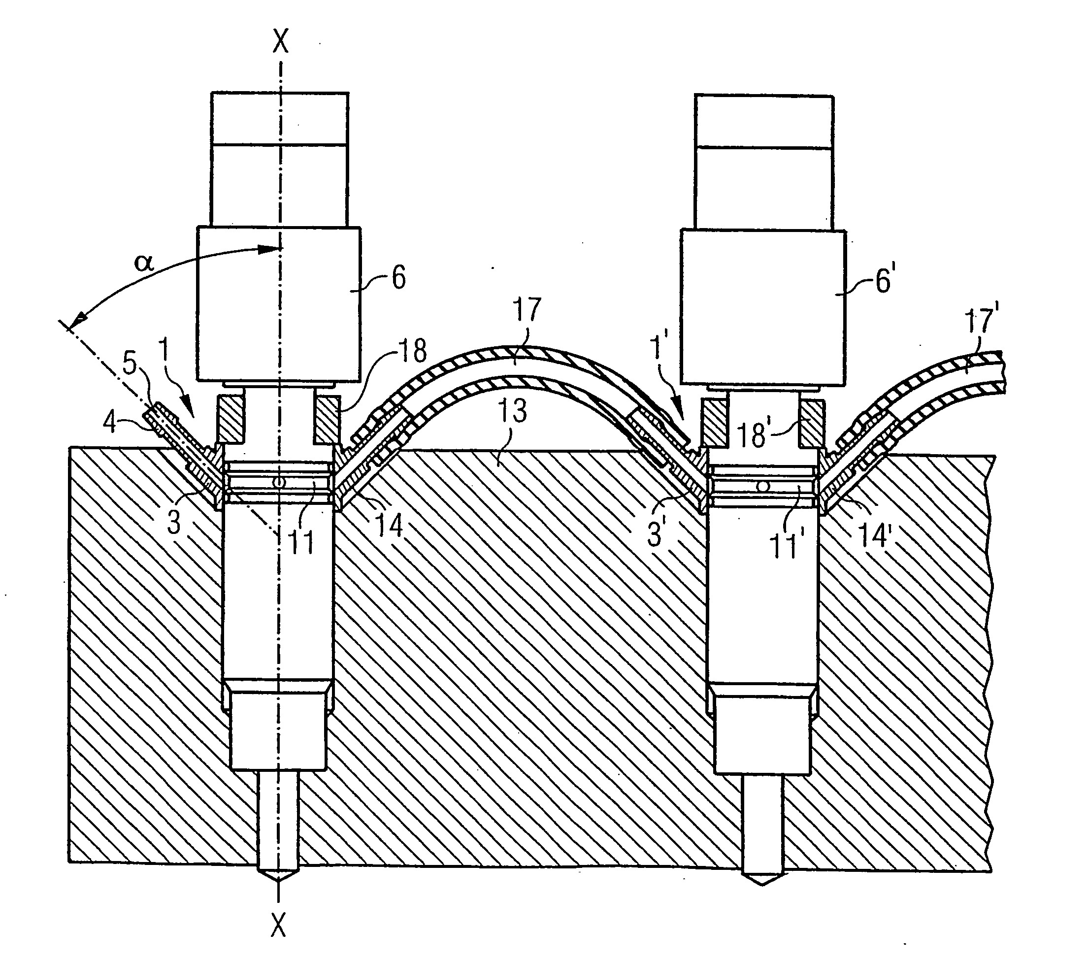
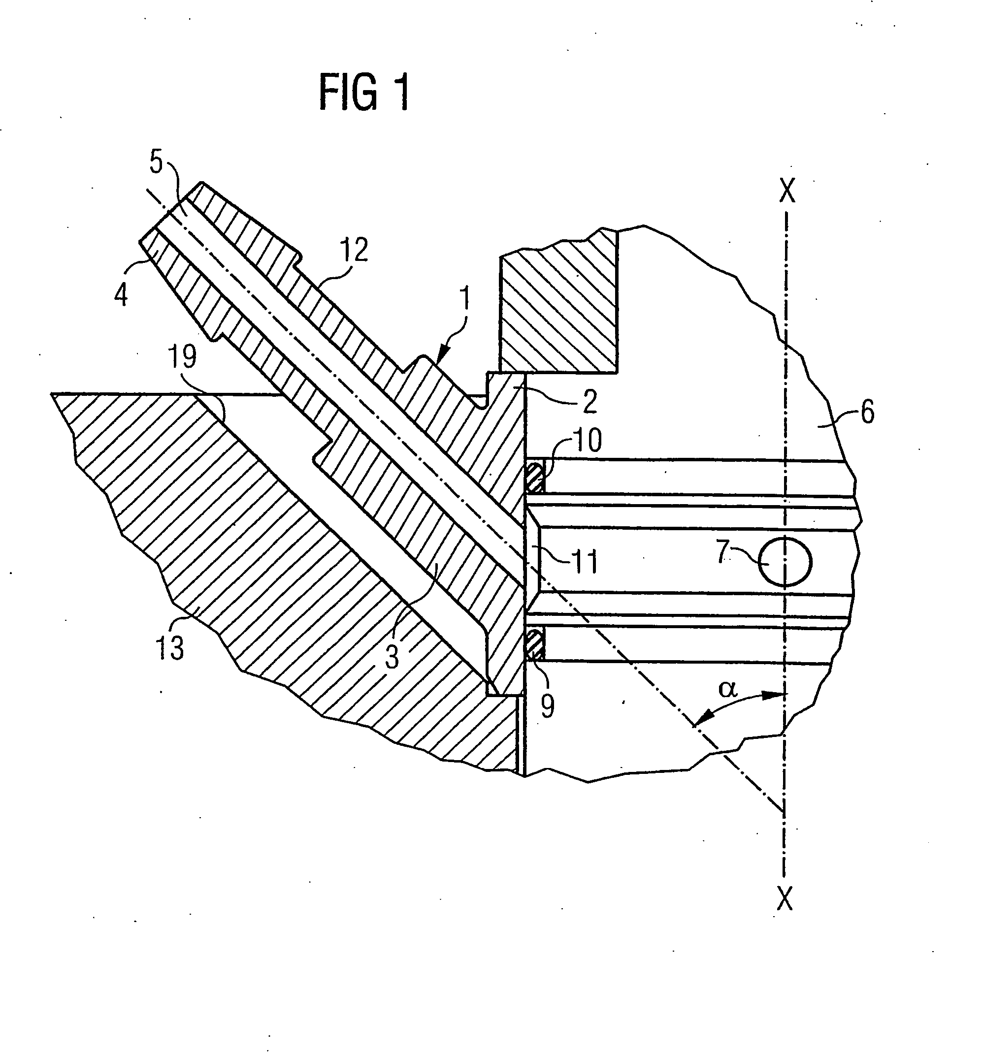
[0037] A first exemplary embodiment of the invention is described below with reference to FIGS. 1 to 3. As shown in FIG. 1, the injector component 1 with integrated leakage connection incorporates a centralizer sleeve 2 as well as an integrated leakage connection 3. The centralizer sleeve 2 is used for centering the fuel injector 6 in a bore in a cylinder head 13 of an internal combustion engine.

[0038] As shown in FIG. 1, the leakage connection 3 incorporates an integrated nipple 4. The leakage connection 3 is constructed at an angle α of approximately 45° to a principle axis of the injector X-X. A corresponding recess 19 for accommodating the leakage connection 3 is constructed in the cylinder head 13. The leakage connection 3 incorporates the integrated nipple 4 and an internal leakage bore 5. Moreover, an undercut 12 is provided to enable a leakage return line (not illustrated) to be securely fastened.

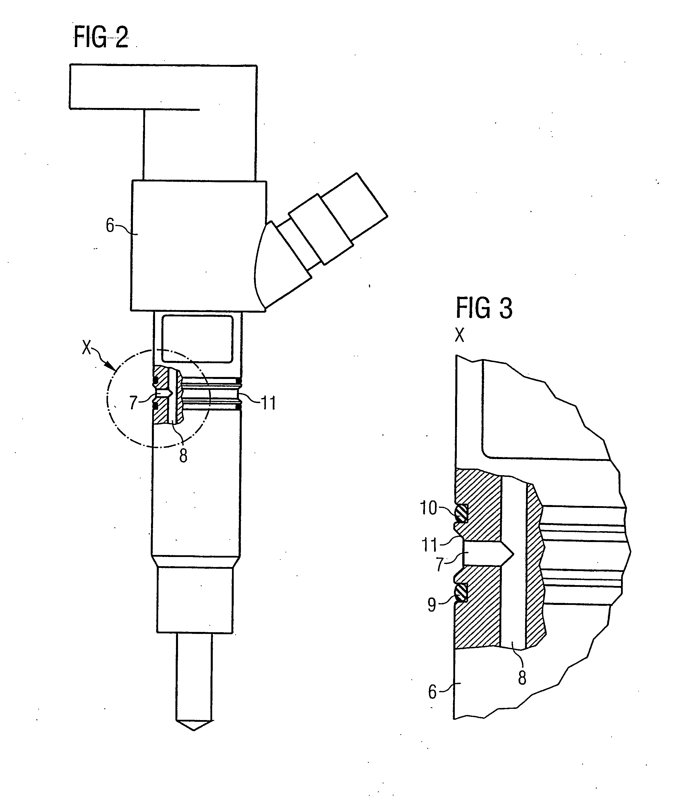
[0039] As shown in FIGS. 2 and 3 in particular, the injector 6 incorporates a...


PUM


Abstract

The invention relates to a leakage connection for an injector, which inject fuel into a combustion chamber of an internal combustion engine. The leakage connection is configured as one piece with an injector component. In addition, a leakage nipple is integrated into the leakage connection, for attaching a leakage return line.

Description

CROSS-REFERENCE TO RELATED APPLICATION OR PRIORITY [0001] This application is a continuation of co-pending International Application No. PCT / DE03 / 01239 filed Apr. 11, 2003, which designates the United States, and claims priority to German application number DE10215980.7 filed Apr. 11, 2002.FIELD OF THE INVENTION [0002] The invention relates to a leakage connection for an injector, which injects fuel into a combustion chamber of an internal combustion engine. BACKGROUND OF THE INVENTION [0003] Accumulator injection systems which operate with very high injection pressures are increasingly being used as fuel supply systems for internal combustion engines. In these accumulator injection systems, fuel is delivered by means of a high-pressure pump into a fuel injector, from which the fuel is injected into the combustion chamber of the internal combustion engine. A fuel injector of this type has an injection valve which is hydraulically opened or closed by a control valve with the help of ...

Claims


Application Information

Patent Timeline
Patent Type & Authority Applications(United States)
IPC IPC(8): F02F1/24F02M55/00F02M55/02F02M61/14
CPCF02M55/002
Inventor MARKSTEINER, DIETERRUBLING, KLAUS
Owner SIEMENS AG
Why Eureka
Try Eureka