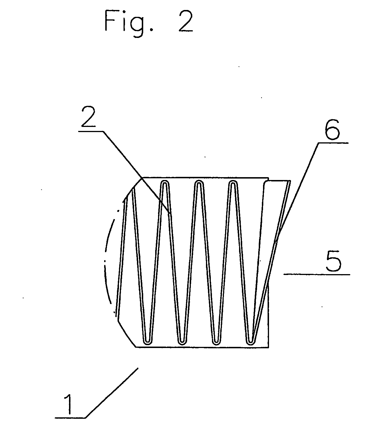
[0008] Surprisingly, it has been found that this design of the end of the filter element, which was originally felt to be defective and undesirable by the inventors and which is attributable, for example, to an incompletely developed
pleat tip geometry of the
filter material during manufacturing, may result in a greatly improved sealing capacity of the filter element against the holding device. The only requirement is that the filter web material be selected or conditioned in the end area of the filter element so that corrugation does not occur when placed against the associated essentially flat wall.
[0009] Once it has been recognized that a convex curvature of the end of the filter element may improve the sealing capacity against the holder, only minor steps need to be taken to prevent the filter web material from corrugating when the outwardly curved, convex end of the filter element is placed against the associated, essentially flat housing wall. For example, it is obvious that the stiffer the filter web material, the easier it is to achieve the effect according to the present invention. It was possible to determine that the undesirable corrugation occurred, in particular, when a very thin, flexible filter web material was used. A
coating, for example, a rubber
coating of the filter web material on the end of the filter element also improves the effect according to the present invention. The term “conditioning” in the sense of the present invention should therefore be understood as being all measures suitable for influencing the properties of the filter web material, for example to stiffen the filter web material, in a manner that largely avoids the aforementioned corrugation.
[0011] Those skilled in the art may easily determine the correct degree of curvature, for example on the basis of a few simple routine experiments, paying attention to housing and filter element tolerances.
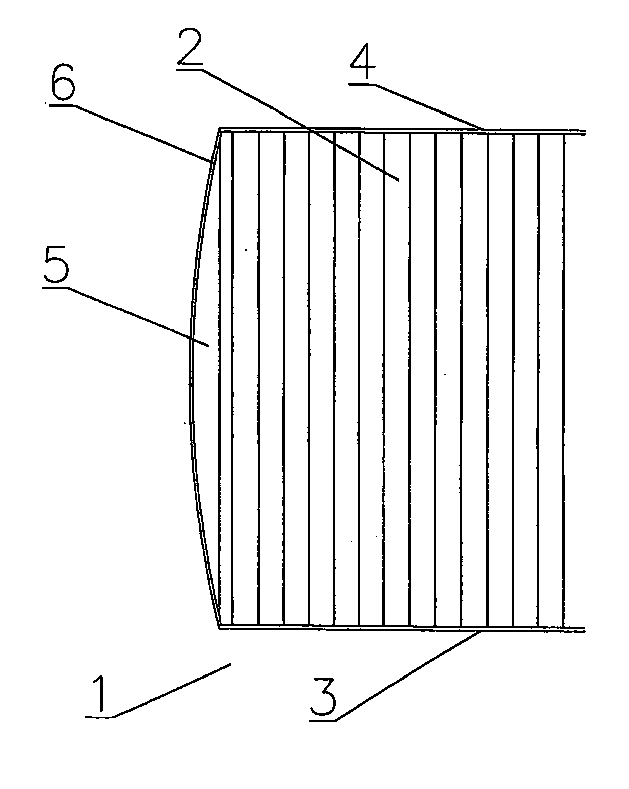
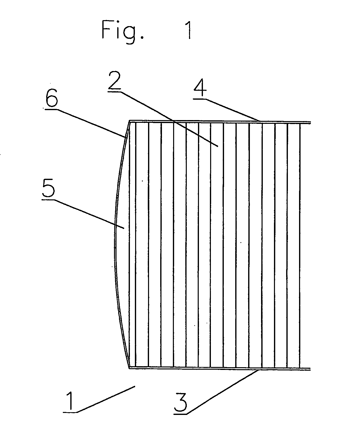
[0012] In a preferred embodiment of the present invention, the filter web has a
pleat runout region at the end, the convex curvature being introduced into the
pleat runout region. This embodiment is very easy and cost-effective to produce. If the nature of the filter web causes a tendency to corrugate when the pleat runout region is placed against the wall of the holding device, the material may be stiffened or impregnated or rubber-coated or similarly treated in this area, for example, as described above. However, the nature of the filter web material itself preferably makes the latter stiff enough to render any auxiliary means of sealing unnecessary.
[0013] A particularly simple arrangement is to use an essentially known combination filter as the filter element. This is understood to be a filter element, usually made of a
nonwoven fabric, whose filter web includes at least one layer of a particle-filtering material and a least one layer of a material that filters
chemical contaminants, in particular an adsorbent material such as
activated carbon. Due to the fact that the filter web is made of multiple
layers of
filter material, it is stiffer than single-layer filters, which prevents corrugation when the curved pleat runout region is placed against the holder wall. To secure the
activated carbon in the
carrier material, combination filters are also usually rubber-coated on the edge of the filter web, which further helps achieve a tight seal. However, a combination filter of the aforementioned type achieves a very tight seal even without this rubber
coating. In particular, the sealing effect is so good that no additional sealing agents are needed. This good sealing effect is achieved solely by the convex curvature of the pleat runout region without using additional sealing and / or reinforcing elements (labyrinth seals, foams, profiles or, in particular, additional nonwoven or
textile edges in a wide range of designs, etc.), which would have to be applied in an additional manufacturing step. This very good sealing effect achieved even without the use of additional sealing or reinforcing elements occurs not only if the end of the holder wall associated with the end of the filter element designed according to the present invention is provided with an essentially flat design, but also if the wall is designed with a slightly convex or concave curvature.
[0014] The filter element according to the present invention may be easily and very economically manufactured, for example, on a
fully automatic selvedge gumming
machine in which the filters are produced by
cutting across a theoretically endless filter web that is pleated in a zigzag manner. As mentioned above, the pleat tip geometries may be incompletely formed, particularly in the case of filter web materials that have a certain degree of stiffness, which ultimately results in the outward curvature of the pleat runout according to the present invention, which was originally considered to be undesirable.

