Skate truck

a technology for skate trucks and wheels, applied in the field of skate trucks, can solve the problems of limiting the rotation range of the hanger of the prior art skate truck to a narrow range, affecting the performance of skate trucks, so as to achieve a wider weight range, different feel, and wider weight range of riders

Inactive Publication Date: 2013-05-28
SBYKE USA
View PDF81 Cites 10 Cited by
  • Summary
  • Abstract
  • Description
  • Claims
  • Application Information

AI Technical Summary

Benefits of technology

[0007]A stable skate truck that provides for a wide yaw angle and weight range of riders is provided. The skate truck has at least three (3) ball bearings that slide within grooves formed in one of either a base or hanger of the skate truck. The grooves match the ball bearings and have a ramp configuration to push the hanger away from the base as the skate truck progresses into a turn. The ramps of the grooves may have different profiles such as regressive, progressive, linear and combinations thereof to provide the rider a different feel as the rider progresses into a turn
[0008]A spring is preloaded and biases the hanger towards the base so that the truck is normally in the straight forward direction. As the skate truck progresses into a turn, the ball bearings slide within the grooves and the spring is compressed to urge the ball bearings back to the center of the ramps and to urge the truck back to the straight forward direction. The spring assists in stabilizing the vehicle. A second component that stabilizes the vehicle is the centrifugal force created as the rider progresses into a turn. The centrifugal force applies a variable downward force on a deck of the vehicle based on the turn radius. The centrifugal force is translated to the ball bearings and urges the ball bearing back to the center of the ramp further urging the truck back to the straight forward direction. Another component that stabilizes the vehicle is the weight of the rider. The weight of the rider also urges the ball bearings back to the center of the ramp. Since the weight of the rider urges the ball bearings back to the center of the ramp, the preload on the spring can be used for a wider weight range of riders.

Problems solved by technology

However, the elastomeric member must be sufficiently rigid so that the rider's weight does not over power the bias force created by the elastomeric member.
These factors limit rotation of the hanger of the prior art skate truck to a narrow range.
Moreover, there is a danger that the elastomeric member may bottom out as the rider progresses into a turn thereby inadvertently lifting the outside wheels of the skate truck.

Method used


Image

  • Skate truck
  • Skate truck
  • Skate truck

Examples


Embodiment Construction

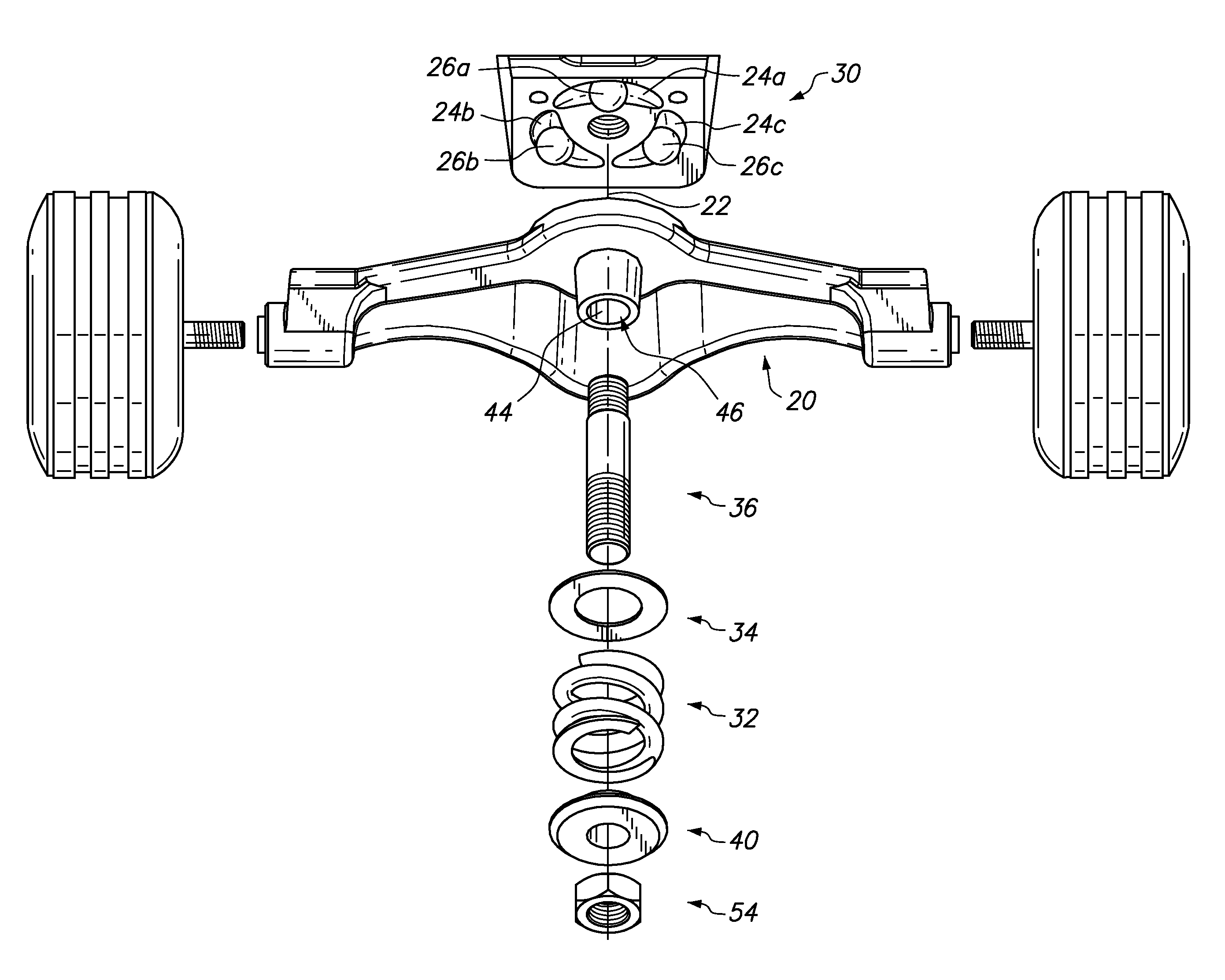
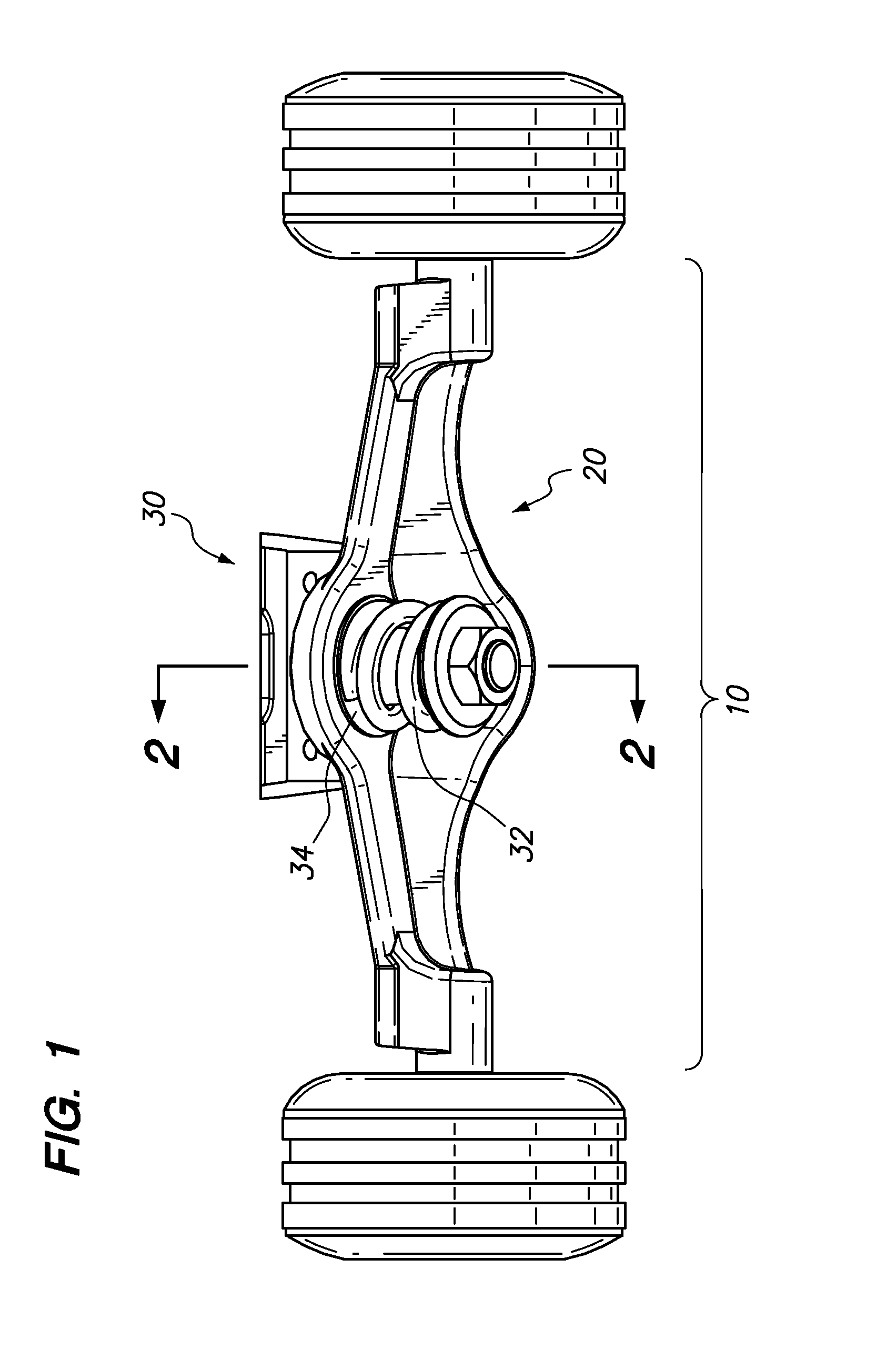
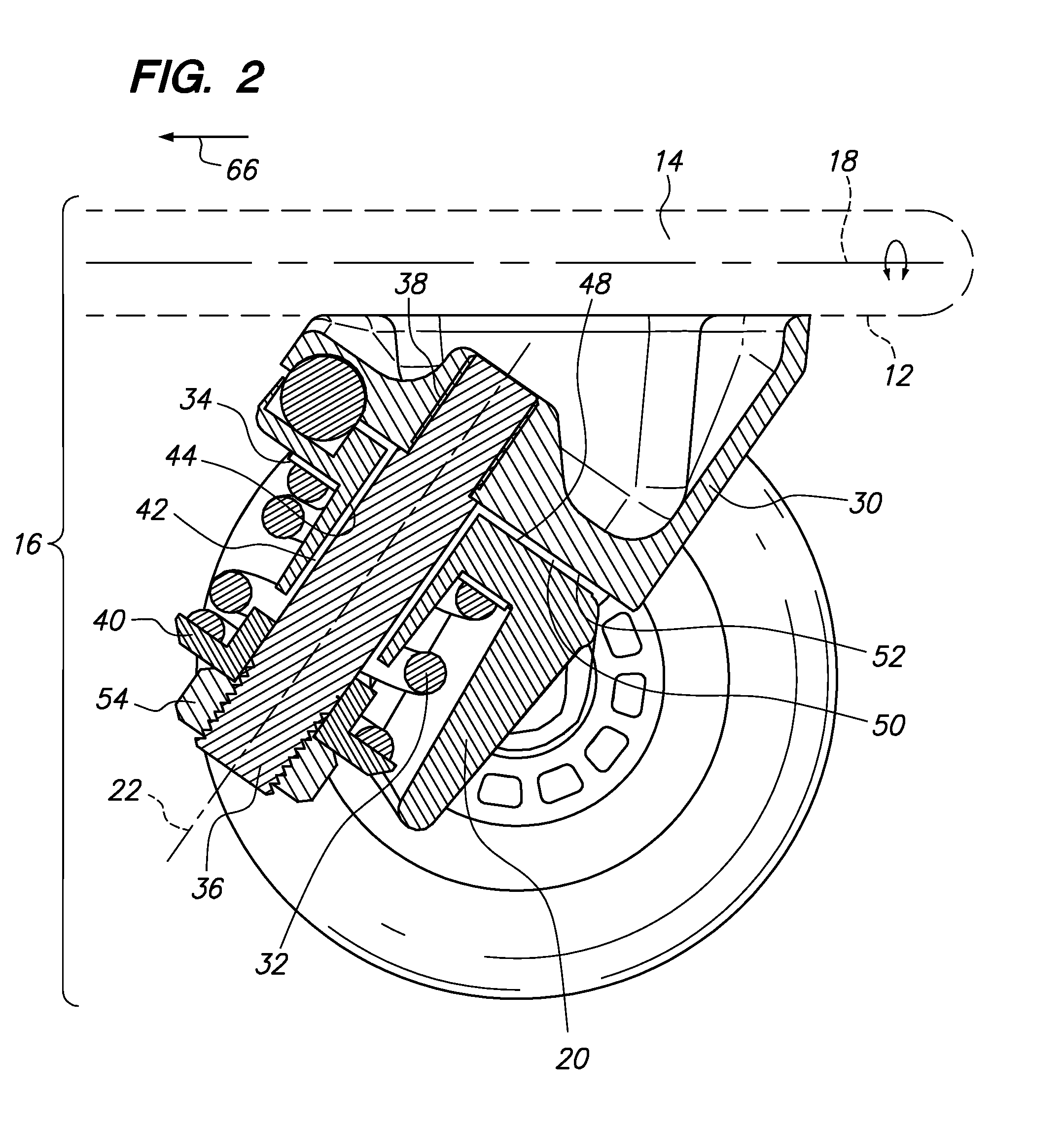
[0034]Referring now to the drawings, a skate truck 10 is shown. The skate truck may be mounted to a bottom surface 12 of a deck 14 of a scooter, skateboard or like vehicle 16 (See FIG. 2). When the deck 14 is rotated about its central longitudinal axis 18 (see FIG. 2), a hanger 20 may be yawed about a pivot axis 22 (See FIG. 3) to turn the vehicle left or right. The pivot axis 22 is defined by three semi-circularly shaped grooves 24a-c and three bearings 26a-c that slide within the grooves 24a-c (see FIG. 4) as the hanger 20 rotates about the pivot axis 22. The bearings 26a-c are seated within mounting recesses 28a-c. The grooves 24a-c may have a ramp profile. The ramp profile may have left and right sides 29a, b (see FIG. 4) which are identical to each other so that as the rider turns left or right, the response of the skate truck 10 is identical on the left and right sides 29a, b. For each of the sides of the ramp profile, the ramp may push the ball bearings 26a-c further away out...


PUM


Abstract

A skate truck is disclosed which provides for a wide yaw angle for a hanger, minimal friction during yawing of the hanger, and a suspension that is dynamically stabilized based on a weight of a rider and a turn radius of a vehicle to which the skate truck is mounted. Additionally, a tension of the skate truck can be adjusted by preloading a spring which accommodates a wide weight ranger of riders. The truck may have a hanger supported between two bearings, namely, a sliding bearing system and a thrust bearing. The sliding bearings slide within grooves that define a pivot axis of the hanger. The grooves can also have various customized ramp profiles to provide a different feel during turning of the vehicle.

Description

CROSS-REFERENCE TO RELATED APPLICATIONS[0001]Not ApplicableSTATEMENT RE: FEDERALLY SPONSORED RESEARCH / DEVELOPMENT[0002]Not ApplicableBACKGROUND[0003]The present invention relates to a truck for a vehicle such as a skateboard or scooter.[0004]Prior art skate trucks are fabricated in the following manner. A hanger of the skate truck pivots about a nose. The hanger is biased to the straight forward neutral position by an elastomeric member. However, the elastomeric member must be sufficiently rigid so that the rider's weight does not over power the bias force created by the elastomeric member. Additionally, the elastomeric member must be pre-tensioned to a specific amount to properly support the weight of the rider. These factors limit rotation of the hanger of the prior art skate truck to a narrow range. Moreover, there is a danger that the elastomeric member may bottom out as the rider progresses into a turn thereby inadvertently lifting the outside wheels of the skate truck.[0005]Ac...

Claims


Application Information

Patent Timeline
Patent Type & Authority Patents(United States)
IPC IPC(8): A63C17/00
CPCA63C17/012
Inventor WILSON, STEPHEN S.
Owner SBYKE USA
Why Eureka
Try Eureka