System for signal transmission by magnetic induction in a near-field propagation mode, with antenna tuning for link budget optimization

a near-field propagation mode and magnetic induction technology, applied in the direction of near-field systems using receivers, electric controllers, instruments, etc., can solve the problem of unoptimized antenna tuning in terms of power consumption of transmitters

Active Publication Date: 2013-05-28
NXP BV
View PDF24 Cites 16 Cited by
  • Summary
  • Abstract
  • Description
  • Claims
  • Application Information

AI Technical Summary

Benefits of technology

[0011]Therefore, it is an object of the invention to improve on the known art, and to more precisely provide for a signal transmission system having a new antenna tuning allowing a link budget optimization.

Problems solved by technology

One can show that this antenna tuning is not optimal in terms of power consumption of the transmitter.

Method used


Image

  • System for signal transmission by magnetic induction in a near-field propagation mode, with antenna tuning for link budget optimization
  • System for signal transmission by magnetic induction in a near-field propagation mode, with antenna tuning for link budget optimization

Examples


Embodiment Construction

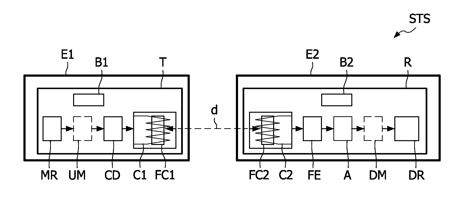
[0029]Reference is initially made to FIG. 1 to describe an example of embodiment of a signal transmission system STS according to the invention.

[0030]A signal transmission system STS comprises a transmitter T arranged for transmitting radio signals and a receiver R arranged for receiving the radio signals transmitted by a transmitter T. In the non limiting example illustrated in FIG. 1, the transmitter T equips a first equipment E1 while the receiver R equips a second equipment E2.

[0031]In the following description it will be considered that the first E1 and second E2 equipments are bidirectional wireless communication equipments, such as wireless telephones and hearing devices. But it is important to notice that the invention is not limited to this type of wireless communication equipment. It applies to any type of wireless communication equipment, and notably to laptops or personal digital assistants (PDAs), provided with a radio communication module, and to telemetry equipments s...


PUM


Abstract

A signal transmission system (STS) comprises a transmitter (T) with a first LC circuit comprising a first coil (C1) intended to be fed with signals having a chosen carrier frequency, and a receiver (R) with a second LC circuit comprising a second coil (C2) and coupled to a circuit front-end (FE). The first coil (C1) is arranged to transfer energy to the second coil (C2) by magnetic induction in a near-field propagation mode. The first LC circuit (C1) has an increased quality factor and is tuned to a first frequency which is shifted in a first direction from the carrier frequency by a first value, and the second LC circuit (C2) has an increased quality factor and is tuned to a second frequency which is shifted in a second direction, opposite to the first one, from the carrier frequency by a second value.

Description

FIELD OF THE INVENTION[0001]The present invention relates to systems intended for signal transmission by magnetic induction in near-field propagation mode.[0002]One means here by “signal transmission system” a system comprising a transmitter with a circuit driver intended to be fed with signals having a chosen carrier frequency and feeding a first transmitting antenna coil, and a distant receiver with a second receiving antenna coil coupled to a circuit front-end, the first coil being arranged to transfer energy to the second coil by magnetic induction in a near-field propagation mode.BACKGROUND OF THE INVENTION[0003]As it is known to those skilled in the art, magnetic induction is one of the technologies used to transmit signals between a transmitter and a receiver, which are parts of some wireless communication equipments, for instance.[0004]The magnetic induction is based on the generation of a quasi-static magnetic field component by a first coil of a transmitter, through which ...

Claims


Application Information

Patent Timeline
Patent Type & Authority Patents(United States)
IPC IPC(8): H04B5/00
CPCH04B5/0093H04B5/02
Inventor NOEL, DENIS
Owner NXP BV
Why Eureka
Try Eureka