Post removal device

a technology for removing devices and posts, applied in lifting devices, fencing, buildings, etc., can solve the problems of difficult removal of posts, etc., and achieve the effect of simple and effective us

Active Publication Date: 2013-06-04
DAVIS GRAEME
View PDF13 Cites 4 Cited by
  • Summary
  • Abstract
  • Description
  • Claims
  • Application Information

AI Technical Summary

Benefits of technology

[0004]It is an object of the invention to provide a post removal device that is relatively simple and effective to use.
[0013]It is further preferred that each of the post grippers include a gripping surface for gripping a post and that that surface be a curved, serrated surface. Such a surface can provide extremely good gripping characteristics against opposite sides of a post.
[0017]In the above arrangement, a sliding member can be employed in sliding connection with the rigid support. In this arrangement, each of the second portion of the lever, the pair of arms, the sliding member and the grippers move together during sliding movement of that member and rotational movement of the grippers between the open and closed conditions occurs when the second portion and the pair of arms move relative to the sliding member. In this arrangement, sliding of the sliding member may terminate when the sliding member engages an abutment or stop and at that point, the second portion and the pair of arms can continue movement relative to the sliding member causing rotational movement of the grippers.
[0021]The extent to which the gripping arrangement can be lifted in the gripping condition can vary depending on the dimensions of the post removal device, but in one arrangement, only a small lift is required in the order of about 100 mm to 150 mm. Where a post requires a greater lift for removal, a second lifting movement can be applied and indeed, a plurality of lifting movements might be required for a typical post to be removed. However, the ease with which the post removal device of the invention can be employed makes this a simple procedure. It is to be noted, that many posts might be removable by hand upon a single lifting movement being applied by the post removal device, so that where post removal is being conducted by two labourers, one labourer can operate the post removal device and the other can lift the post after a lifting movement of the device has taken place.

Problems solved by technology

Removing the post is often difficult, given that they are usually very firmly embedded in the ground, which usually also has had time to settle about the post.

Method used


Image

  • Post removal device
  • Post removal device
  • Post removal device

Examples


Embodiment Construction

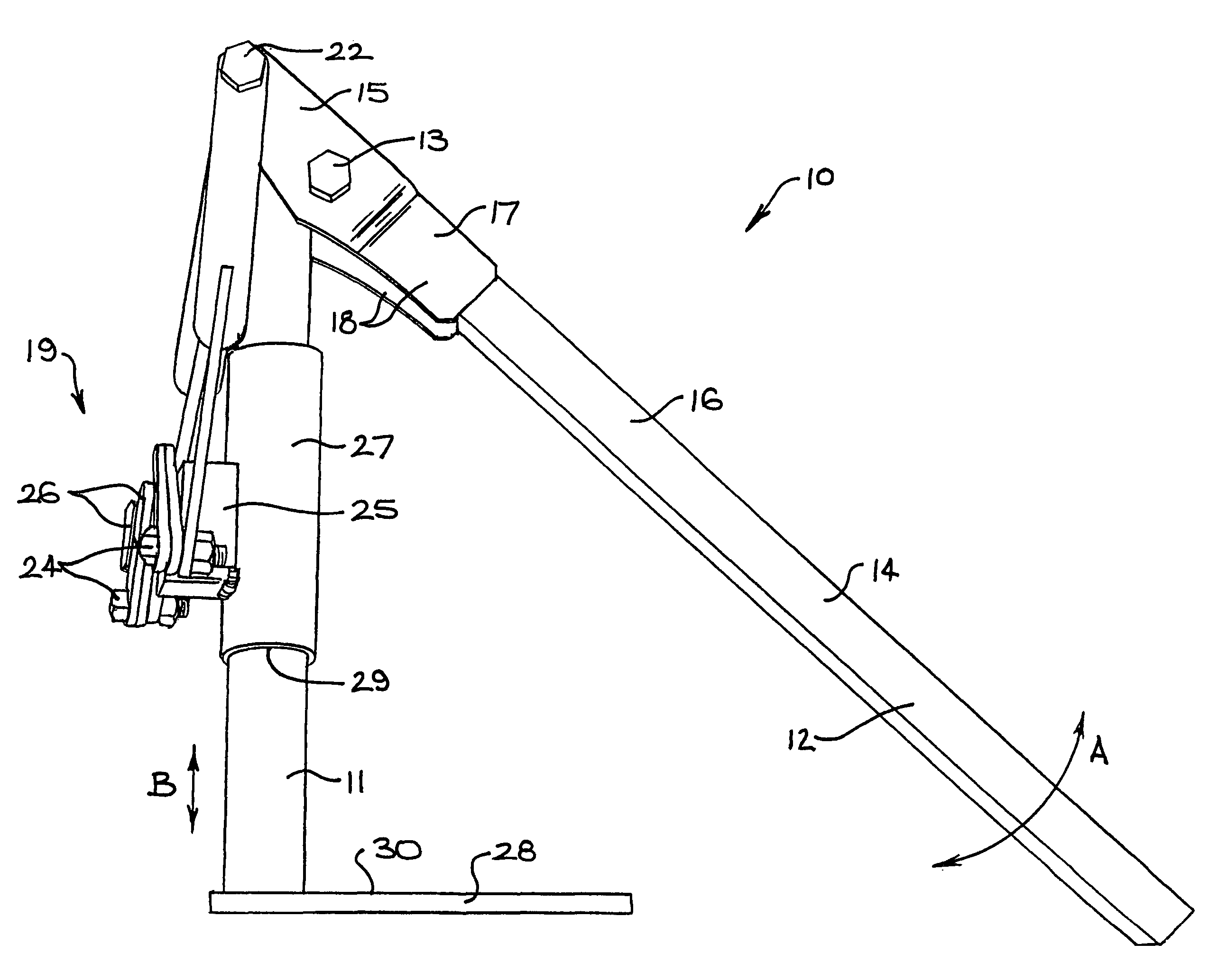
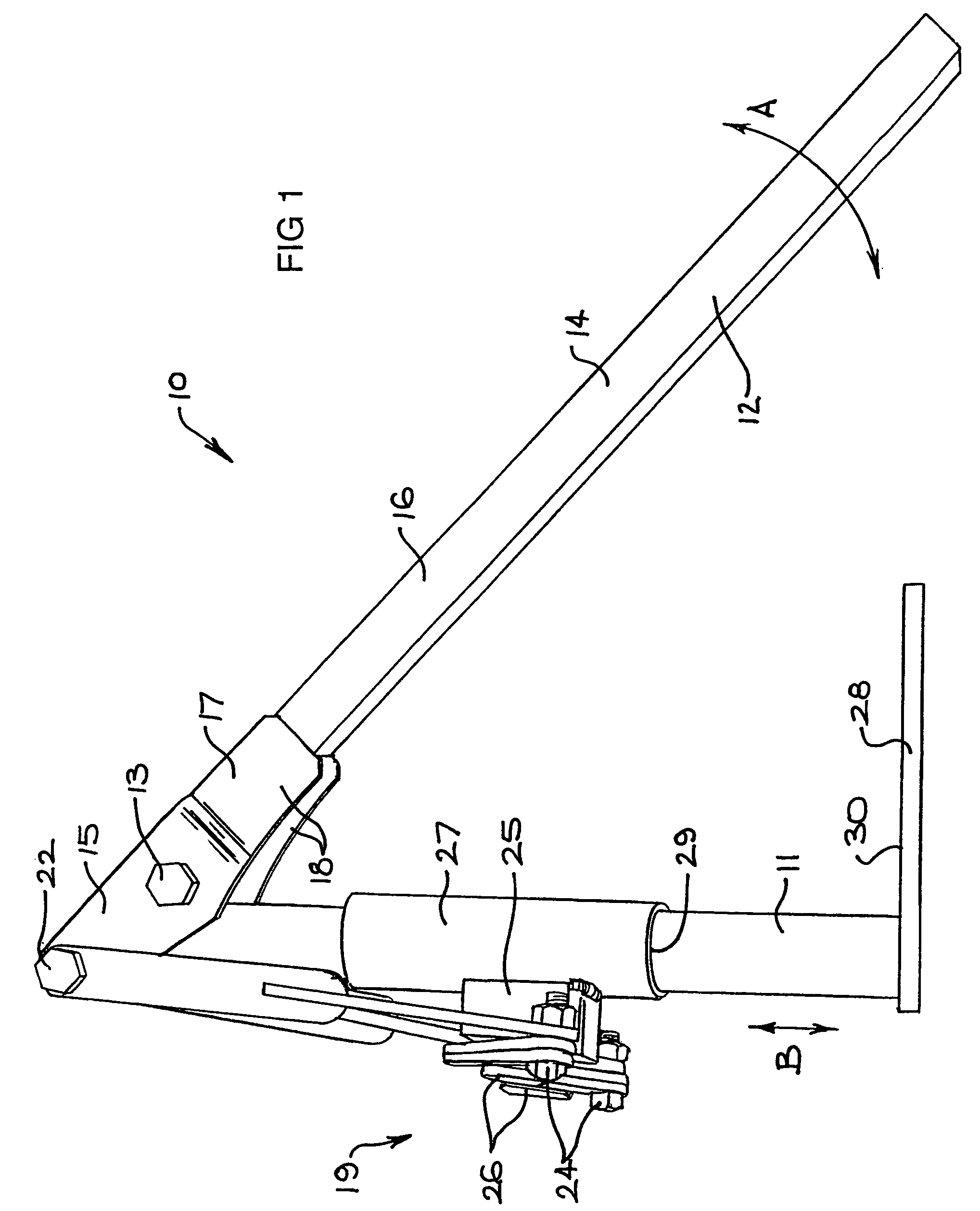
[0026]FIG. 1 is a side view of a post removal device according to one embodiment of the invention. The device 10 includes a rigid support 11 which defines a fulcrum in the form of an axle 13 about which a lever 12 is rotatable. The actual axle is not shown in FIG. 1, although the head of the axle 13 is shown. The axle 13 is connected to the support 11 and allows pivoting of the lever 12 thereabout in a substantially vertical plane shown by the arrow A. In FIG. 1, the lever 12 is at the bottom of a rotational stroke.

[0027]The lever 12 extends on either side of the axle 13 to define a first portion 14 on the right hand side and a second portion 15 on the left hand side according to FIG. 1. It is evident from FIG. 1, that downward movement of the first portion 14 will result in upward movement of the second portion 15 and vice versa.

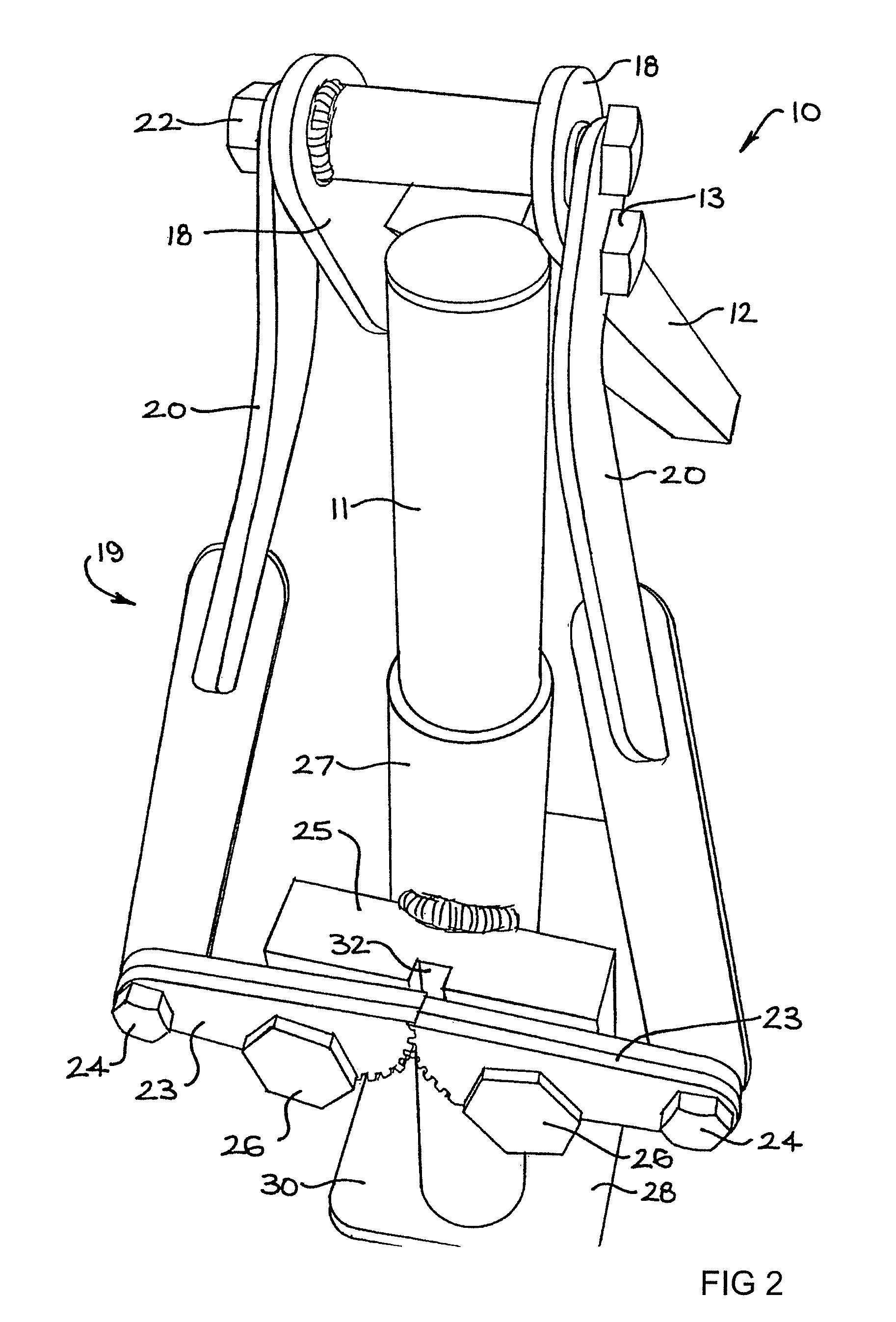
[0028]The lever 12 is formed from a section 16 of square metal bar and a bifurcated section 17. The bifurcated section 17 includes a pair of arms 18 which ...


PUM


Abstract

A post removal device (10), including a support (11), and a lever (12) which is rotatable about a fulcrum (13). The lever (12) extends on either side of the fulcrum (13) to define a first portion (14) and a second portion (15), whereby downward movement of the first portion (14) results in upward movement of the second portion (15). The second portion (15) is connected to a gripping arrangement (19) which includes a pair of post grippers (23), which are movable during rotation of the lever (12), from an open condition to a gripping condition. The extent of rotational movement of the lever (12) is sufficient for the grippers (23) to move from the open condition to the gripping condition and for the gripping arrangement (19) to be lifted with the grippers (23) in the gripping condition for lifting a post.

Description

FIELD OF THE INVENTION[0001]The present invention relates to a post removal device for removing posts from the ground.BACKGROUND OF THE INVENTION[0002]The present invention has been developed principally for the removal of posts known as “star pickets”. This type of post has a cross-section comprising three planar members, which extend radially from a central axis and which are spaced apart equidistantly at 120°. Posts of this type are frequently used on building sites and in temporary installations such as sporting and other entertainment events. In most cases, the posts have to be removed after a period of time. Removing the post is often difficult, given that they are usually very firmly embedded in the ground, which usually also has had time to settle about the post.[0003]Various devices have been proposed before to remove posts such as star pickets. See for example AU 2005201795 and U.S. Pat. No. 6,527,250. Applicant is not aware that the device of either of these prior art doc...

Claims


Application Information

Patent Timeline
Patent Type & Authority Patents(United States)
IPC IPC(8): B66F3/00
CPCE04H17/265
Inventor DAVIS, GRAEME
Owner DAVIS GRAEME
Why Eureka
Try Eureka