Electronic torque wrench

a torque wrench and electric technology, applied in the field of tools, can solve the problems of increased torque, click noise, pretension of the fastener,

Active Publication Date: 2013-07-16
GAUTHIER BIOMEDICAL
View PDF39 Cites 65 Cited by
  • Summary
  • Abstract
  • Description
  • Claims
  • Application Information

AI Technical Summary

Problems solved by technology

This stretch results in the pretension in the fastener which then holds the components together.
Clicker type torque wrenches work by preloading a snap mechanism with a spring to release at a specified torque, thereby generating a click noise.
For a hand held tool, in order to drive fasteners, typically the user will have to change their grip or change hands in order to keep driving the fastener due to the limitation of the range of motion of the bones joint in a human hand, which occurs at approximately 100 to 180 degrees depending on the person.
Therefore, when torquing operations are init

Method used


Image

  • Electronic torque wrench
  • Electronic torque wrench
  • Electronic torque wrench

Examples


second embodiment

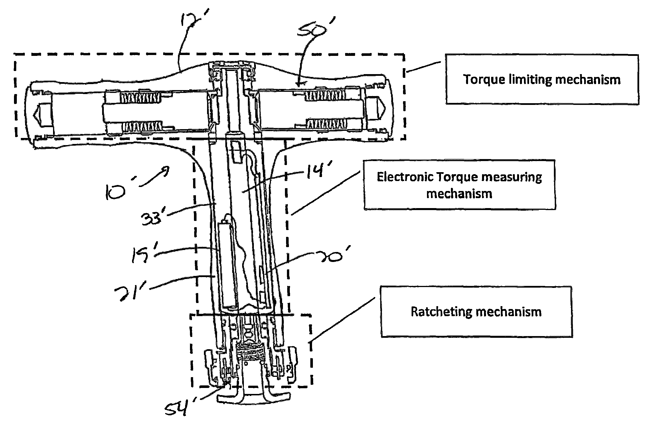
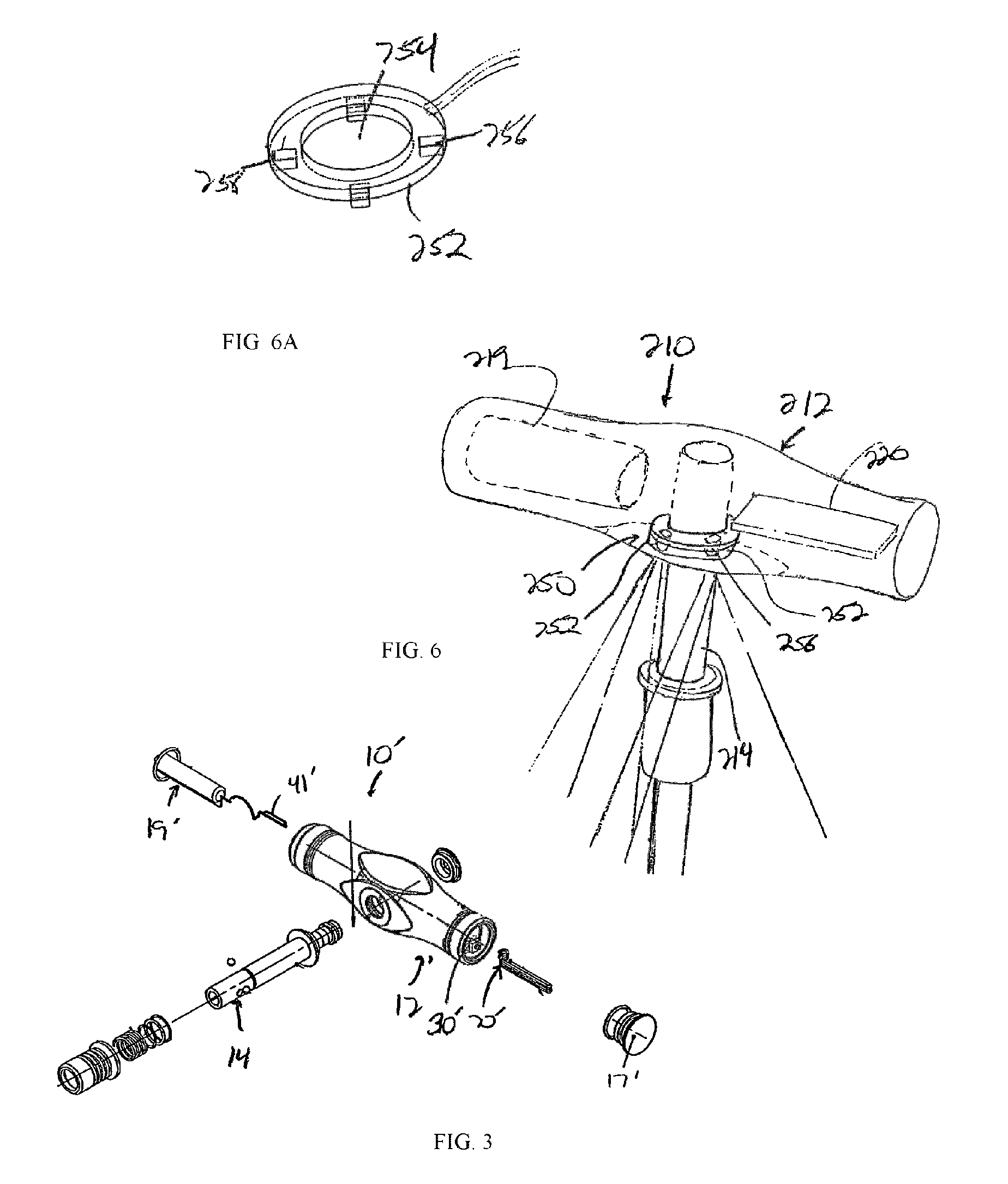
[0061]Referring now to FIGS. 3 and 4, the wrench 10′ is illustrated. In this embodiment, the wrench 10′ has a T-shape, with the shaft 14′ extending perpendicularly from the body 12′ in which is disposed a housing 18′, and over which is located a handle 16′. In the illustrated embodiment, the shaft 14′ is disposed centrally on the body 12′ and extends perpendicularly from the body 12′ with the end 26′ and adapter 28′ spaced therefrom, such that the power source 19′ and the electronics unit 20′ are disposed on opposite sides of the body 12′ and connected to one another by connectors 41′, while still contained within the barrier 33′. Alternatively, the shaft 14′ can be oriented to one side or the other of the body 12′, as desired.

[0062]The shaft 14′ can be connected directly to the body 12′ or to a ratcheting mechanism (not shown) disposed within the body 12′. At the connection of the shaft 14′ to the body 12′, a sensor 30′ is disposed to determine the strain or torque being applied by...

third embodiment

[0063]Referring now to FIG. 5, the wrench 110 is illustrated. The wrench 110 has a T-shape similar to the embodiment of FIGS. 3 and 4, but includes a piezoelectric sensor 130 within the handle 116. The sensor 130 is formed of a first element 132 on a flat surface 133 of the shaft 114 and a second element 134 is disposed on an adjacent flat surface 135 of the body 112. The relative position of the elements 132 and 134 is determined by the electronics unit 120 disposed in the barrier 133, which is connected to the elements 132 and 134 by conductors 136, 141 to receive signals from the elements 132 and 134 for use in operating the display 122.

[0064]Looking now at FIGS. 6 and 6A, a driving tool or wrench 210 is shown similar to that in FIGS. 3-5, in which the wrench 210 additionally includes a light source 250. The light source 250 is formed with a generally circular housing 252 that has a central aperture 254 that is slightly larger in shape than the shaft 214, such that the housing 25...

fourth embodiment

[0067]Looking now at FIG. 9, the wrench 510 is illustrated. In the wrench 510, the body 512, in addition to the ratcheting mechanism 515 and other components of the prior embodiments 10 and 10′, has a mechanical torque level measuring and / or indication mechanism 570, such as that disclosed in U.S. Pat. No. 7,806,026, incorporated herein by reference in its entirety. The pop-out indication mechanism 570 operates in conjunction with the display 522 to illustrate the particular torque level at which the wrench 510 is being operated.


PUM


Abstract

A torque wrench for use in driving fasteners is provided. The wrench includes an electronics unit disposed within a body of the wrench that is capable of sensing and measuring the torque applied to a fastener by the wrench and providing an output of the level of torque to the user. The electronics unit is also disposed within a barrier in the body that isolates the unit from the exterior environment around the wrench. The data sensed by the electronics unit can be utilized to provide feedback to the user regarding the operation of the wrench, and to monitor the overall operation of the wrench for calibration purposes, among other functions. During use, the wrench can provide the user with visual, audible and tactile feedback regarding the operation of the device relative to stored maximum torque values stored in the electronics unit.

Description

CROSS-REFERENCE TO RELATED APPLICATIONS[0001]This application claims priority from U.S. Provisional Application Ser. No. 61 / 345,817, filed on May 18, 2010, the entirety of which is hereby expressly incorporated herein.FIELD OF THE INVENTION[0002]The present invention relates to tools, and more specifically to tools including electronic measuring and display device for providing indication of the forces being applied by the tools.BACKGROUND OF THE INVENTION[0003]Often, fasteners used to assemble performance critical components are tightened to a specified torque level to introduce a “pretension” in the fastener without damaging the substrate in which the fastener is positioned. As torque is applied to the head of the fastener, beyond a certain level of torque the fastener begins to stretch. This stretch results in the pretension in the fastener which then holds the components together. A popular method of tightening these fasteners is to use a torque wrench. Accurate and reliable tor...

Claims


Application Information

Patent Timeline
IPC IPC(8): B25B23/144B25B23/16
CPCA61B17/8875A61B2090/066A61B2090/0813B25B23/1425B25B23/14
Inventor GAUTHIER, MICHAEL T.BRAGANZA, AUSTIN R. S.JEUTTER, DEAN C.GAUTHIER, STACY A.FEDDER, RONALD J.
Owner GAUTHIER BIOMEDICAL
Why Eureka
Try Eureka