Surgical stapling instrument comprising a magnetic element driver

a technology of magnetic element and surgical stapling, which is applied in the direction of surgical staples, surgical forceps, dynamo-electric converter control, etc., can solve the problems of surgeons not having a hand free to perform another step in the surgical procedure, and the force required to form the staples and incise the tissue at the same tim

Active Publication Date: 2013-08-27
CILAG GMBH INT
View PDF1354 Cites 1473 Cited by
  • Summary
  • Abstract
  • Description
  • Claims
  • Application Information

AI Technical Summary

Problems solved by technology

In certain circumstances, however, the force required to form the staples and incise the tissue simultaneously may be significant.
While such surgical instruments can be suitable in many circumstances, a surgeon may not have a hand free to perform another step in the surgical procedure.

Method used


Image

  • Surgical stapling instrument comprising a magnetic element driver
  • Surgical stapling instrument comprising a magnetic element driver
  • Surgical stapling instrument comprising a magnetic element driver

Examples


Embodiment Construction

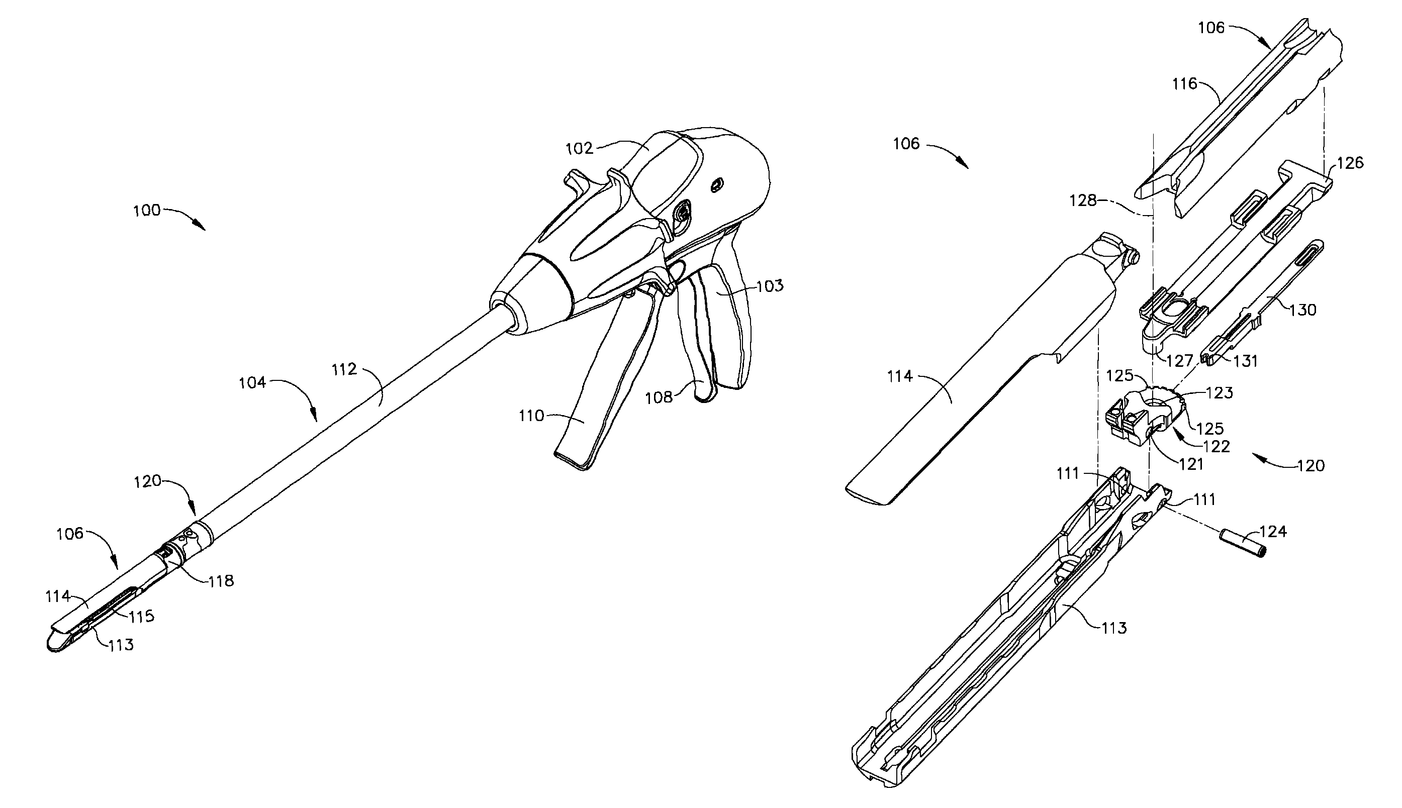
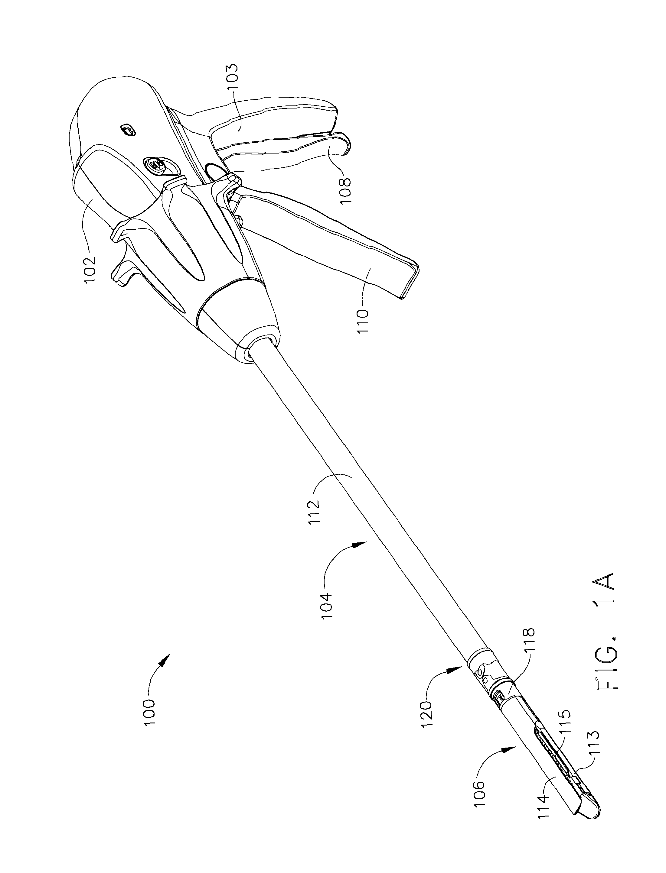
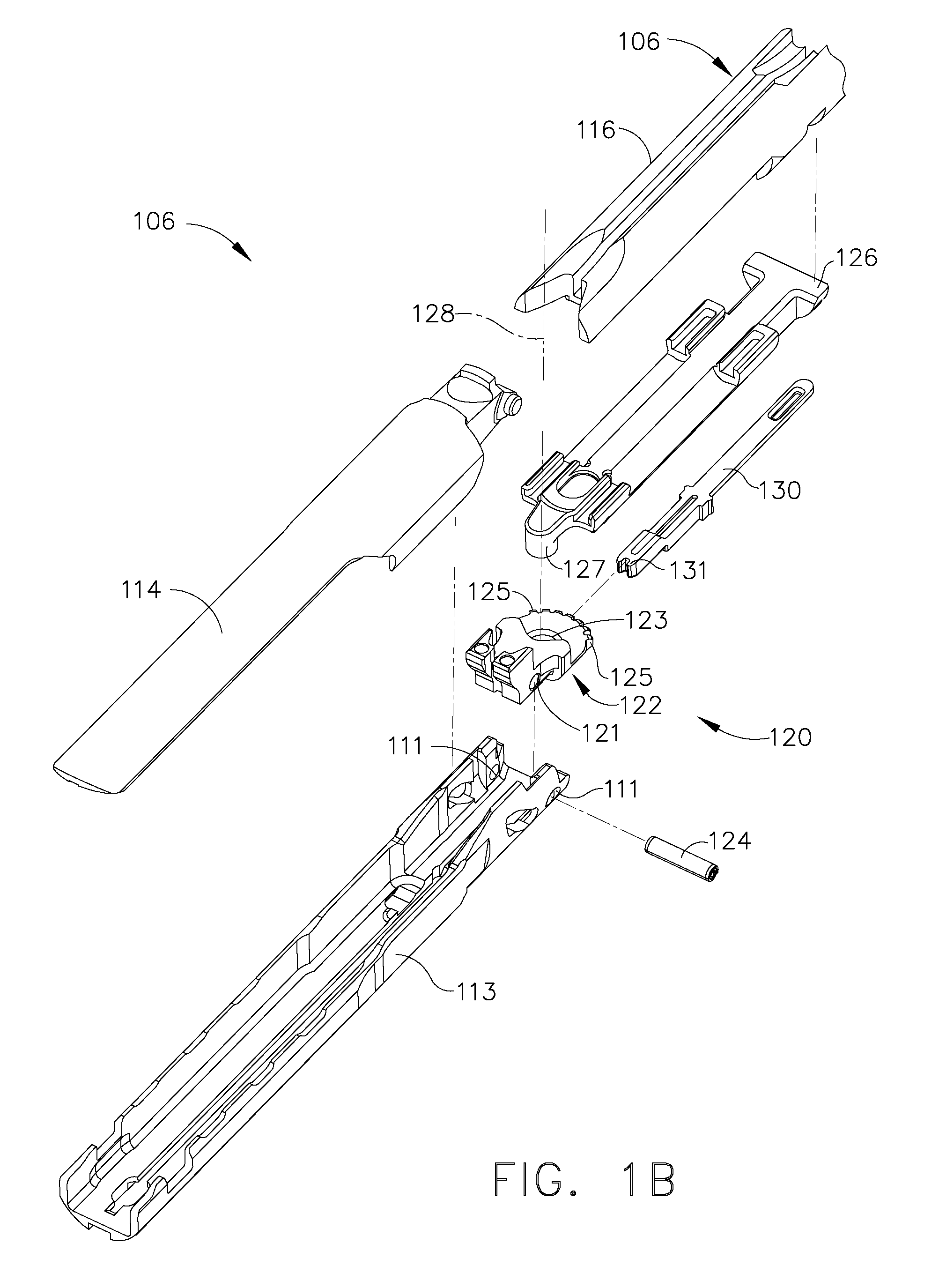
[0071]Certain exemplary embodiments will now be described to provide an overall understanding of the principles of the structure, function, manufacture, and use of the devices and methods disclosed herein. One or more examples of these embodiments are illustrated in the accompanying drawings. Those of ordinary skill in the art will understand that the devices and methods specifically described herein and illustrated in the accompanying drawings are non-limiting exemplary embodiments and that the scope of the various embodiments of the present invention is defined solely by the claims. The features illustrated or described in connection with one exemplary embodiment may be combined with the features of other embodiments. Such modifications and variations are intended to be included within the scope of the present invention.

[0072]The disclosures of the following commonly-owned, contemporaneously-filed United States Patent Applications are incorporated herein by reference in their enti...


PUM

PropertyMeasurementUnit
magnetic fieldaaaaaaaaaa
magneticaaaaaaaaaa
perimeteraaaaaaaaaa

Abstract

In various embodiments, a surgical stapling instrument can comprise a plurality of magnetic elements configured to articulate an end effector of the surgical instrument. The surgical instrument can comprise at least one electromagnet which can be selectively activated, or polarized, to generate a magnetic field sufficient to motivate a second magnetic element, such as a permanent magnet and / or an iron core, for example, mounted to the end effector. In certain embodiments, a surgical stapling instrument can comprise a plurality of magnetic elements configured to open and / or close an end effector of the surgical instrument. In at least one embodiment, a surgical stapling instrument can comprise a plurality of magnetic elements configured to advance and / or retract a firing bar, cutting member, and / or staple sled within the surgical instrument in order to incise and / or staple tissue positioned within an end effector of the surgical instrument.

Description

BACKGROUND[0001]i. Technical Field[0002]The present invention relates, in general, to surgical instruments and, more particularly, to surgical stapling instruments.[0003]ii. Background of the Related Art[0004]Surgical stapling instruments have been used to simultaneously make an incision in tissue and apply lines of staples on opposing sides of the incision. Such instruments commonly include a pair of cooperating jaw members that, if the instrument is intended for endoscopic or laparoscopic applications, are capable of passing through a cannula passageway. In various embodiments, one of the jaw members can receive a staple cartridge having at least two laterally spaced rows of staples. The other jaw member can define an anvil having staple-forming pockets aligned with the rows of staples in the cartridge. The instrument can further include a plurality of wedges, or a staple sled, which, when driven distally, passes through openings in the staple cartridge and engages drivers support...

Claims


Application Information

Patent Timeline
Patent Type & Authority Patents(United States)
IPC IPC(8): A61B17/10
CPCA61B17/07207A61B17/105A61B17/068A61B2017/00398A61B2017/2929A61B2017/2927
Inventor SCHEIB, CHARLES J.JAWOREK, GARY S.HALL, STEVEN G.
Owner CILAG GMBH INT
Why Eureka
Try Eureka