

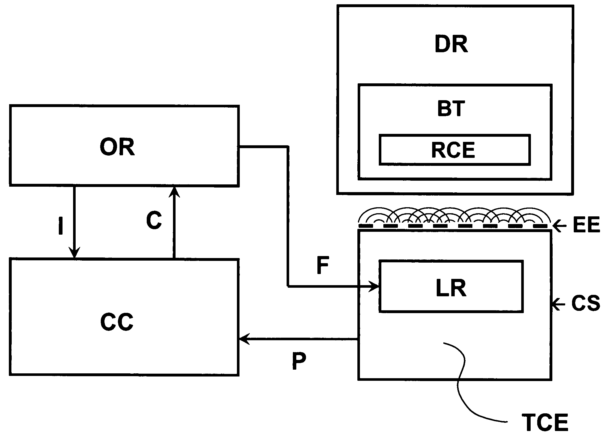
System for transferring energy wirelessly
a wireless energy and wireless technology, applied in electromagnetic wave systems, transformers, inductances, etc., can solve the problems of wasting energy into the environment, c, and still problematic energy transfer by electromagnetic waves
- Summary
- Abstract
- Description
- Claims
- Application Information
AI Technical Summary
Benefits of technology
Problems solved by technology
Method used
Image

Examples
Embodiment Construction
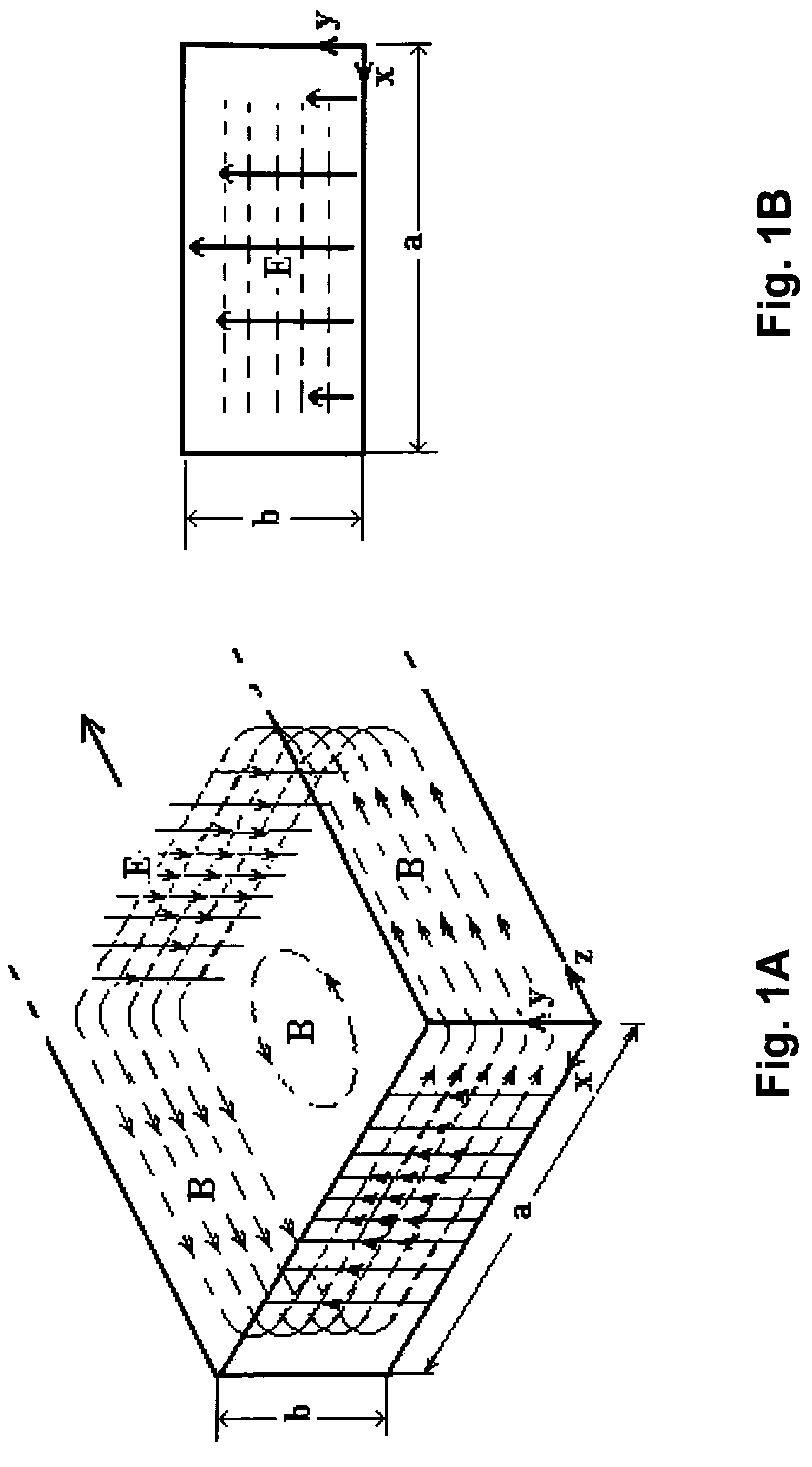
Theoretical Considerations on Electromagnetic Fields
[0046]Maxwell's equations are a set of four differential equations that are basic for the study of electromagnetic phenomena. In fact, they govern the space and time evolution of electric and magnetic fields; in other words, they express relations between electric field, magnetic field, electric charge, electric current, time and spatial coordinates. These equations are well known and are the following:
[0047]{∇·E=ρε0∇×E=-∂B∂t∇·B=0∇×B=μ0J+ε0μ0∂E∂t
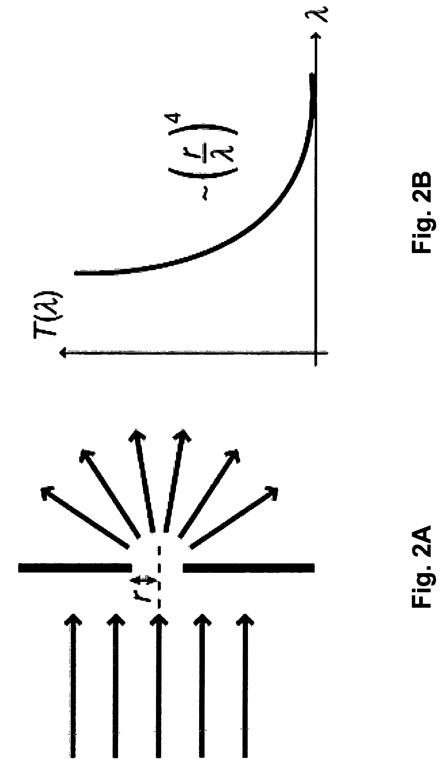
[0048]If a source of electromagnetic waves is considered in the open space, these equations provide a solution for E (electric field) and B (magnetic field) that identifies three spherical and concentric space regions:
[0049]
type of fieldname of regiondistancenon-radiative field / evanescent fieldReactive regionR<0.62D3λ / near radiative fieldFresnel region0.62D3λ<R<2D2λfar radiative fieldFraunhofer regionR>2D2λ
wherein D is the size of the source emitting electromagnetic wa...
PUM
| Property | Measurement | Unit |
|---|---|---|
| size | aaaaa | aaaaa |
| size | aaaaa | aaaaa |
| size | aaaaa | aaaaa |
Abstract
Description
Claims
Application Information