Barrel mounting and retention mechanism

a barrel and mounting technology, applied in the field of gas operated firearms, can solve the problems of increasing the difficulty and time required for the change of barrels, and the complexity of the changeout of barrels

Active Publication Date: 2013-09-24
REM TML HLDG LLC
View PDF20 Cites 85 Cited by
  • Summary
  • Abstract
  • Description
  • Claims
  • Application Information

AI Technical Summary

Problems solved by technology

The changeout of barrels is, however, complicated by the use of various hand guards and accessory rail assemblies typically mounted about the barrels of such firearms, as well as the increasing use of monolithic or one-piece receiver and hand guard assemblies.
Typically, such hand guards must be removed from the firearm prior to the removal and replacement of the barrel, increasing the difficulty and time required for barrel change-out.

Method used


Image

  • Barrel mounting and retention mechanism
  • Barrel mounting and retention mechanism
  • Barrel mounting and retention mechanism

Examples


Embodiment Construction

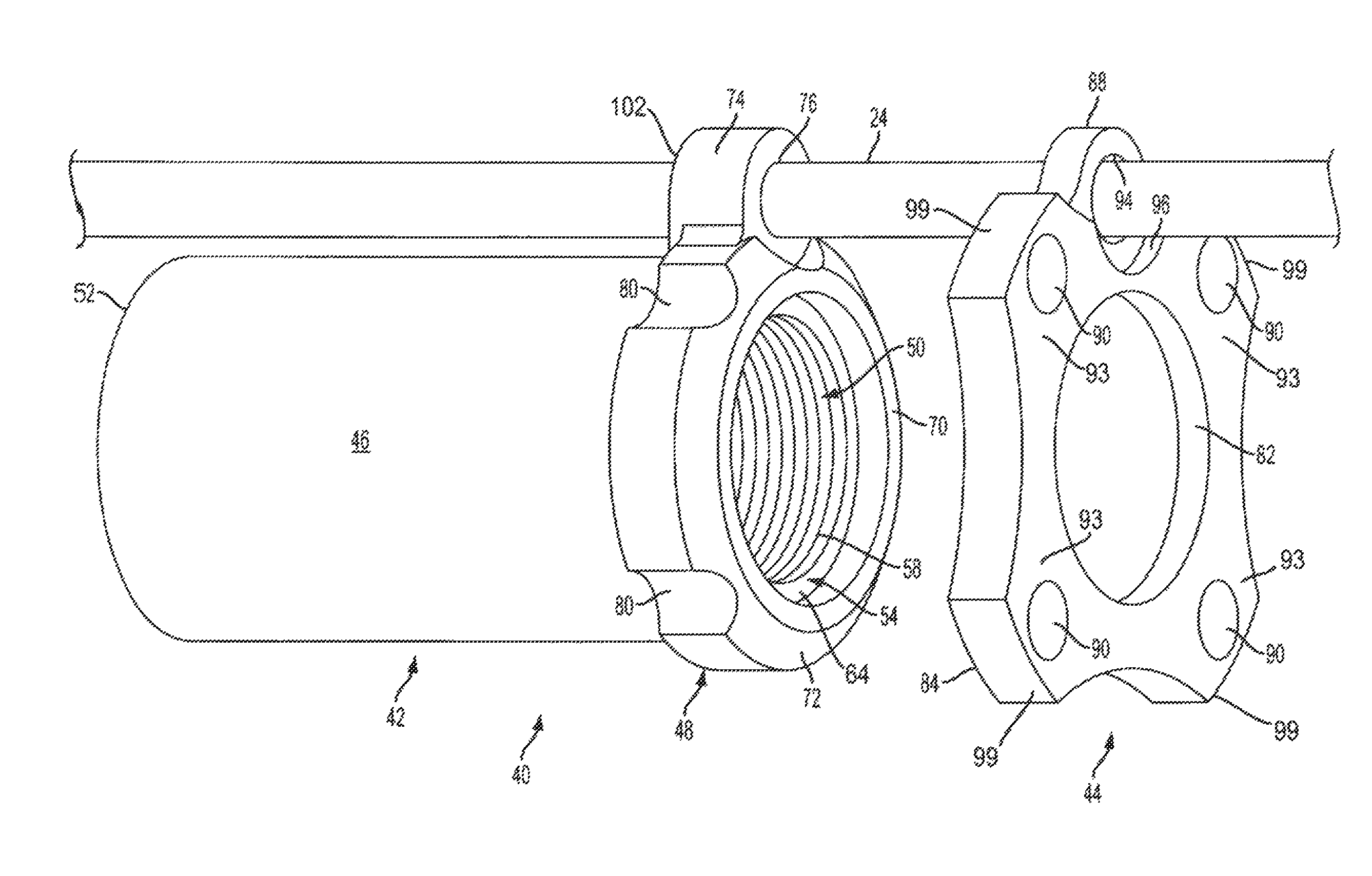
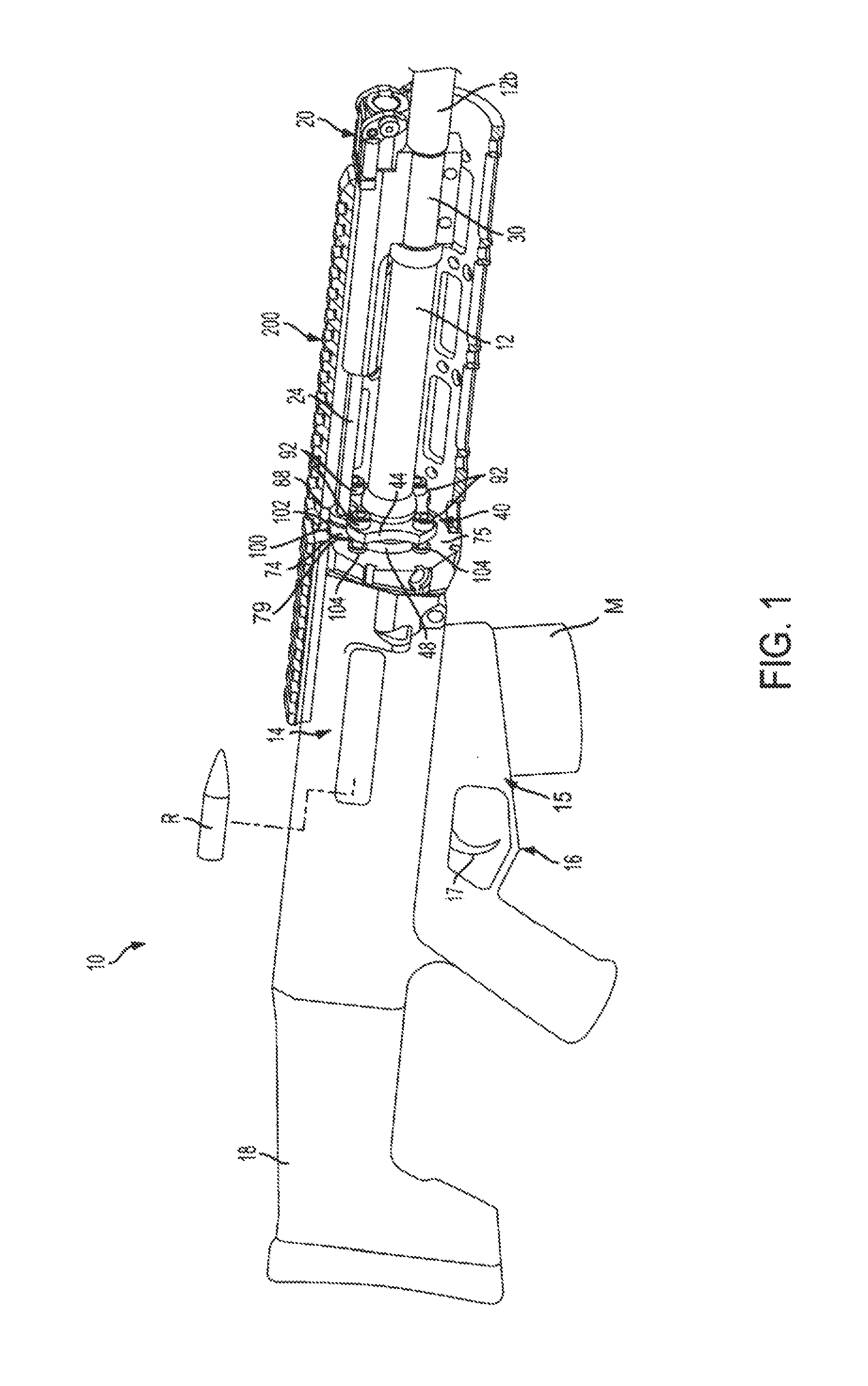
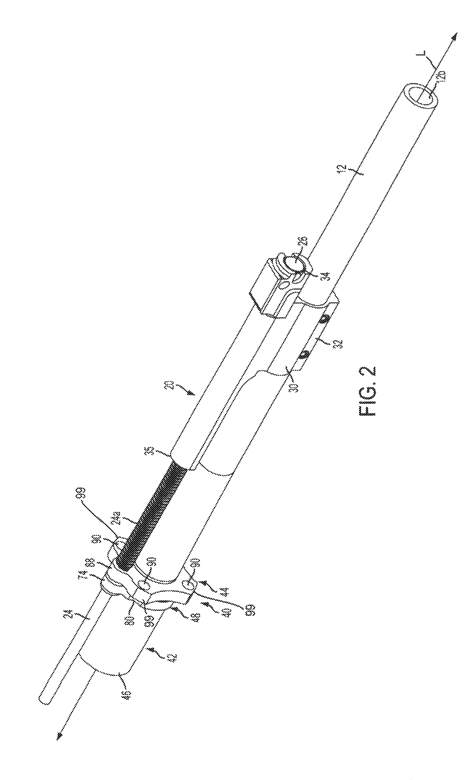
[0016]Referring now to the drawings in which like numerals indicate like parts throughout the several views, the figures illustrate one example embodiment of the barrel mounting and retention apparatus or system according to the principles of the present disclosure for use in a firearm such as an M4, M16, AR-15, SCAR, AK-47, HK416, ACR or similar type gas operated firearm. However, it will be understood that the principles of the barrel mounting and retention device of the present invention can be used in various types of firearms including shotguns, rifles and other long guns, hand guns, and other gas-operated firearms. The following description is provided as an enabling teaching of exemplary embodiments; and those skilled in the relevant art will recognize that many changes can be made to the embodiments described. It also will be apparent that some of the desired benefits of the embodiments described can be obtained by selecting some of the features of the embodiments without ut...


PUM


Abstract

A barrel mounting and retention device for attaching a barrel to a receiver of a firearm. The barrel mounting and retention device can include a barrel extension disposed at a proximal end of the barrel, with an annular collar extending from the barrel extension and defining a first clamp face. A mounting plate having a second clamp face and defining a first axial bore fits over the barrel of the firearm with the barrel extending through the first axial bore. At least a portion of the second clamp face abuts a portion of the first clamp face as the mounting plate is secured to the barrel extension for mounting and retaining the barrel in communication with the receiver of the firearm.

Description

TECHNICAL FIELD[0001]Embodiments of the disclosure are directed generally to gas operated firearms and, more particularly, to an apparatus for mounting a barrel to the receiver of a gas-operated firearm.BACKGROUND INFORMATION[0002]Semi-automatic firearms, such as rifles and shotguns, are designed to fire a round of ammunition, such as a cartridge or shot shell, in response to each squeeze of the trigger of the firearm, and thereafter automatically load the next shell or cartridge from the firearm magazine into the chamber of the firearm. During firing, the primer of the round of ammunition ignites the propellant inside the round, producing an expanding column of high pressure gases within the chamber and barrel of the firearm. The force of this expanding gas propels the bullet / shot of the cartridge or shell down the barrel.[0003]In some types of semi-automatic rifles and shotguns, a portion of the expanding gases will be directed through a duct or port that interconnects the barrel ...

Claims


Application Information

Patent Timeline
Patent Type & Authority Patents(United States)
IPC IPC(8): F41A21/00
CPCF41A21/485F41A21/482
Inventor KENNEY, DANIEL E.RONKAINEN, JAMES W.MATTESON, DAVID O.WILKINSON, LUKE T.
Owner REM TML HLDG LLC
Why Eureka
Try Eureka