Personal lifting device

a technology of lifting device and lifting pad, which is applied in the field of personal lifting device, can solve the problems of limiting the versatility and usefulness of the device, not being able to move the individual shoulder or leg of a patient, and not being able to adjust either side of the lift pad

Inactive Publication Date: 2013-10-08
TINDALL JARY EDWARD
View PDF12 Cites 9 Cited by
  • Summary
  • Abstract
  • Description
  • Claims
  • Application Information

AI Technical Summary

Benefits of technology

[0013]Further, each of the first, second, third and fourth lift lines extends through an opening in the housing. A lift line roller assembly is mounted in the housing adjacent each opening. Each lift line roller assembly engages one of the first, second, third and fourth lift lines so that the lift lines may pass freely through the openings without binding against the housing even when positioned at an unusual angle during operation of the device.

Problems solved by technology

While such devices provide good stability and are useful for their intended purpose, driving more than one lift line with a single motor limits the versatility and usefulness of the devices.
For example, in the absence of independent control of each lift-line it is not possible to move the individual shoulder or leg of a patient or to adjust for lift-line or strap tension if one side becomes elongated or stretched more than the other.
In the absence of individual, independent lift-line control it is not possible to adjust either side of the lift pad for any imbalance that might occur due to a patient being positioned off center on the pad.
Further, the devices cannot be used to effectively roll the patient onto their side in either direction.
Still further, if either one of the lift motors fails, that end of the lift pad cannot be moved in either direction.
Such motors mandate the use of electronic braking devices which not only increase the capital cost of the equipment but add a layer of technology that requires maintenance and could potentially fail which could result in a patient fall.
Further, the physical manipulation of the patient is often difficult and painful for the patient.
The physical exertion required by the caregiver may tax the individual or cause injury if it isn't beyond the caregiver's capability.

Method used


Image

  • Personal lifting device
  • Personal lifting device
  • Personal lifting device

Examples


Embodiment Construction

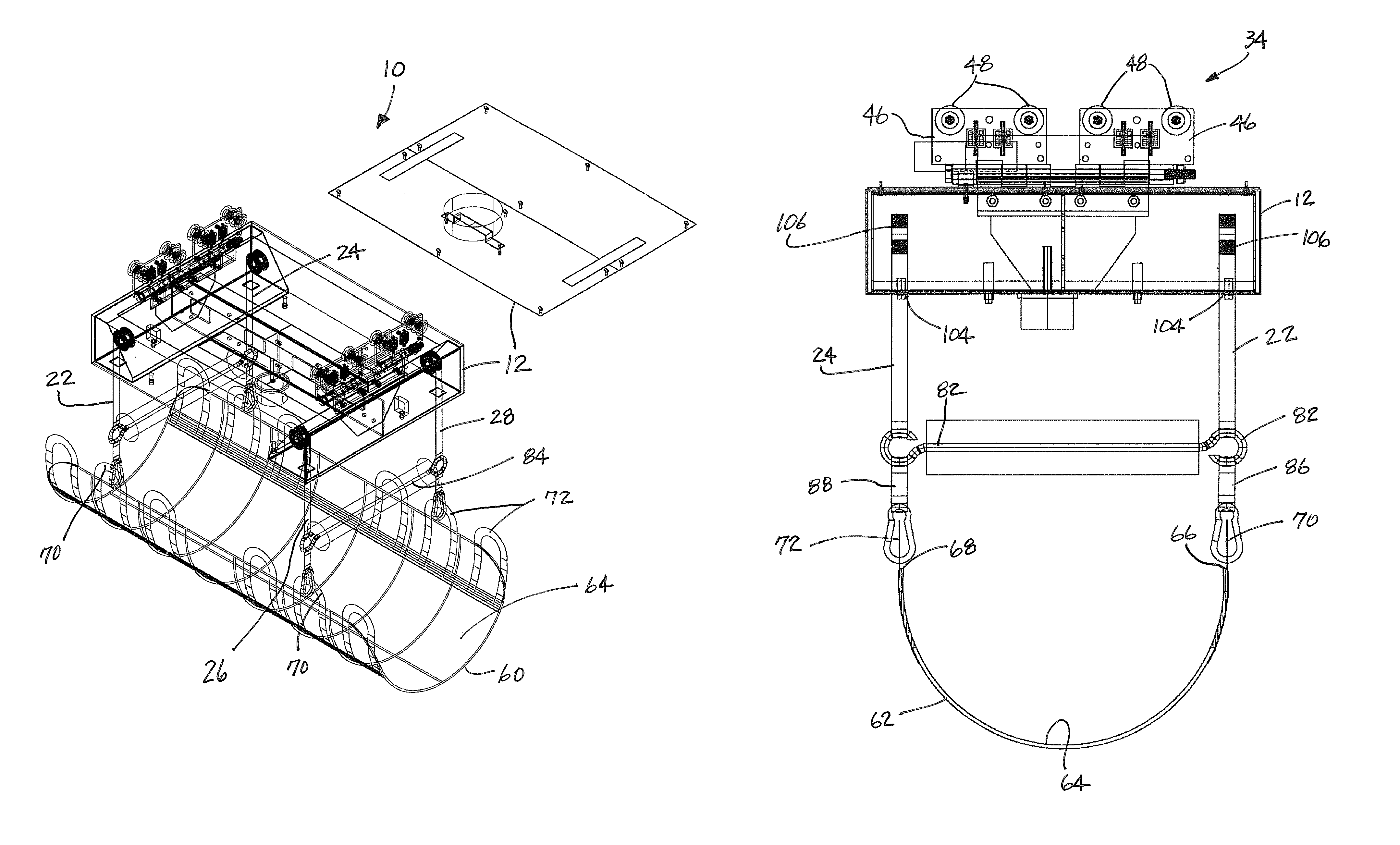
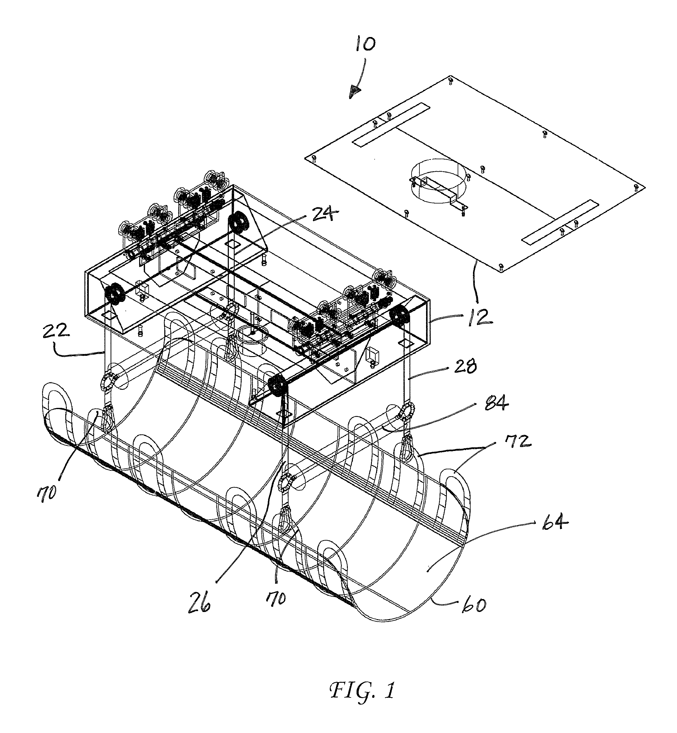
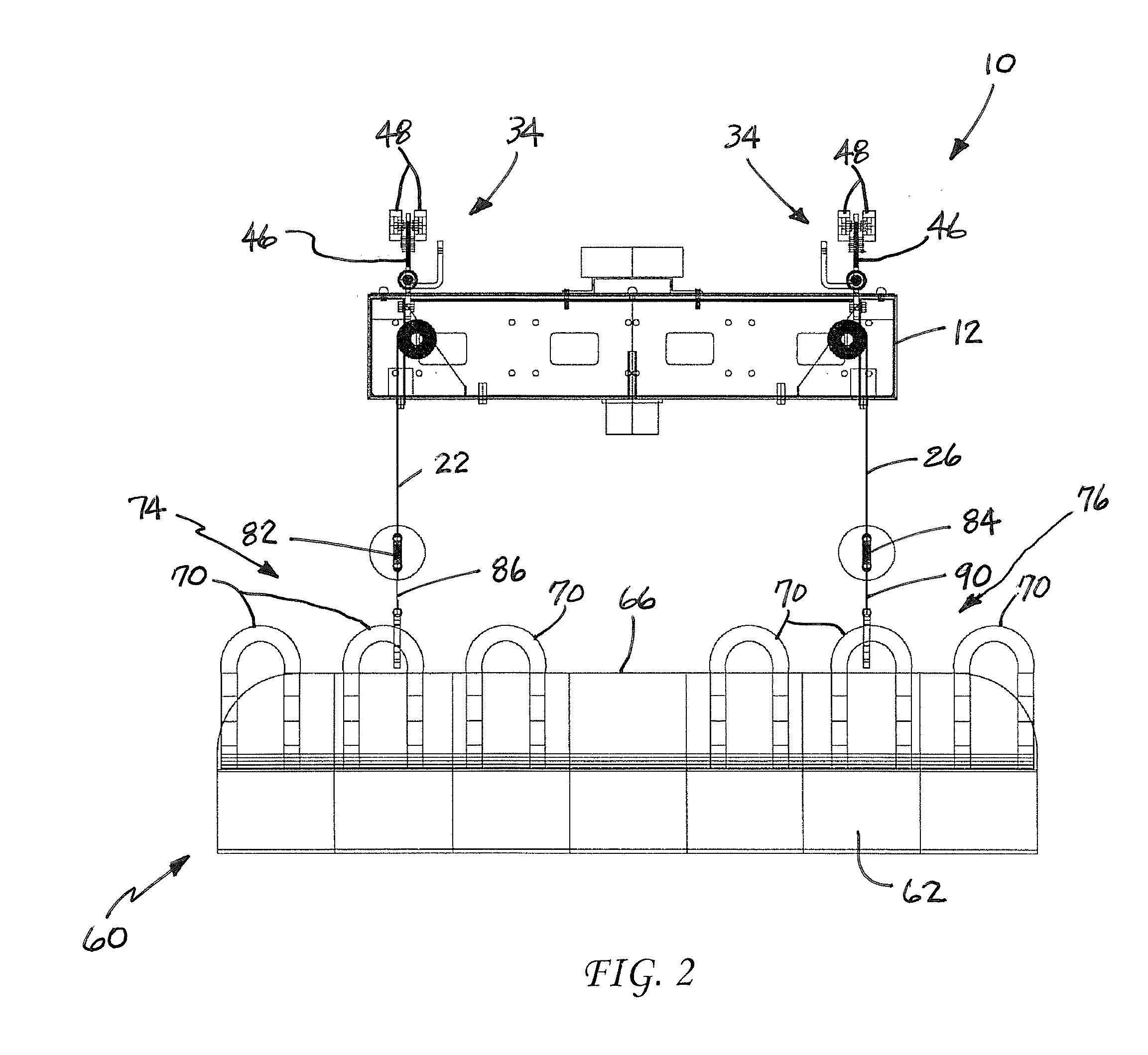
[0026]Reference is now made to FIGS. 1-5 illustrating the personal lifting device 10 of the present invention. The lifting device 10 includes a housing 12 containing a first lifting mechanism 14, a second lifting mechanism 16, a third lifting mechanism 18 and a fourth lifting mechanism 20. More specifically, the first lifting mechanism 14 is carried on the housing 12 adjacent the first corner of the housing, the second lifting mechanism 16 is carried on the housing 12 adjacent the second corner of the housing, the third lifting mechanism 18 is carried on the housing 12 adjacent the third corner of the housing and the fourth lifting mechanism 20 is carried on the housing 12 adjacent the fourth corner of the housing. A first lift line 22 is connected to the first lifting mechanism 14. A second lift line 24 is connected to the second lifting mechanism 16. A third lift line 26 is connected to the third lifting mechanism 18. A fourth lift line 28 is connected to the fourth lifting mechan...


PUM


Abstract

A personal lifting device includes a housing that carries first, second, third and fourth lifting mechanisms. First, second, third and fourth lift lines are connected to the respective lifting mechanisms. Further, the device includes a controller for selectively operating the first, second, third and fourth lifting mechanisms whereby the first, second, third and fourth lifting lines are independently extended and retracted as desired to lower and lift a person.

Description

[0001]This application is a national stage of International Application no. PCT / US10 / 51587 filed on 6 Oct. 2010 which claims the benefit of U.S. provisional patent application Ser. No. 61 / 249,081 filed on 6 Oct. 2009.TECHNICAL FIELD AND INDUSTRIAL APPLICABILITY OF THE INVENTION[0002]The present invention relates generally to the field of mobility devices and, more particularly, to a personal lifting device that may be used to raise or lower a physically disabled individual or patient.BACKGROUND OF THE INVENTION[0003]Personal lifting devices for the purpose of assisting in the raising or lowering of immobilized or physically disabled patients are well known in the art. U.S. Pat. Nos. 4,627,119 and 6,006,377 both disclose lifting devices that are useful to raise and lower patients between prone, inclined and sitting positions. The apparatus disclosed in these documents include four-point lifting systems incorporating four separate lift lines. It should be appreciated, however, that on...

Claims


Application Information

Patent Timeline
Patent Type & Authority Patents(United States)
IPC IPC(8): A61G7/10
CPCA61G7/1015A61G7/1042A61G7/1055A61G7/1061A61G2200/34
Inventor TINDALL, JARY EDWARD
Owner TINDALL JARY EDWARD
Why Eureka
Try Eureka