

Debris deflector and knife for string trimmer
a deflector and string trimmer technology, applied in metal working equipment, agriculture, agricultural tools and machines, etc., can solve the problems of limited size and shape of guards and shrouds mounted on cutting heads or shafts above rotating strings, and insufficient protection of workers
- Summary
- Abstract
- Description
- Claims
- Application Information
AI Technical Summary
Benefits of technology
Problems solved by technology
Method used
Image

Examples
first embodiment
[0035]the combined deflector and knife apparatus 21 of the invention, shown in FIGS. 2 to 8, operates to cut vegetative, such as grass, weeds, hay and plants and direct the cut debris 18 laterally away from workperson 12. Debris 18 does not impinge on legs 19 and feet 20 of happy workperson 12. Apparatus 21 has a knife 22 and deflector 23 mounted on the top wall 24 of shroud 14. Knife 22 located adjacent the front of the shroud side wall 26 extends inwardly above the circular path of cord 17. As shown in FIGS. 4 and 6 to 8, knife 22 has a downwardly extended front wall 27 joined to a horizontal top wall 28. Fasteners 36 and 37, shown as nut and bolt assemblies, mount top wall 28 on top of shroud wall 24. Knife 22 has a radial knife section 29 joined to the bottom of front wall 27. The front of knife section has a pair of cutting edges 30 and 31. An upwardly and outwardly curved finger 32 separates cutting edges 30 and 31. A second upwardly and outwardly curved finger 33 separates cu...
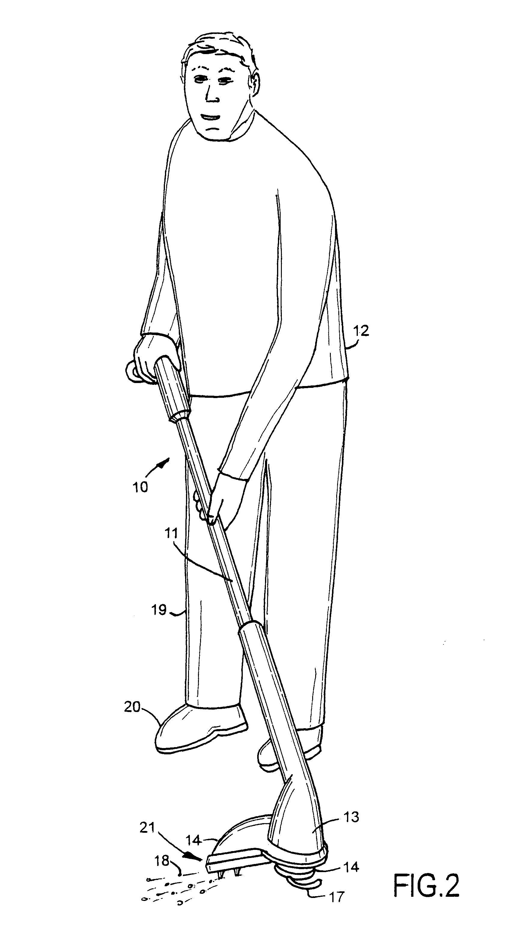
second embodiment
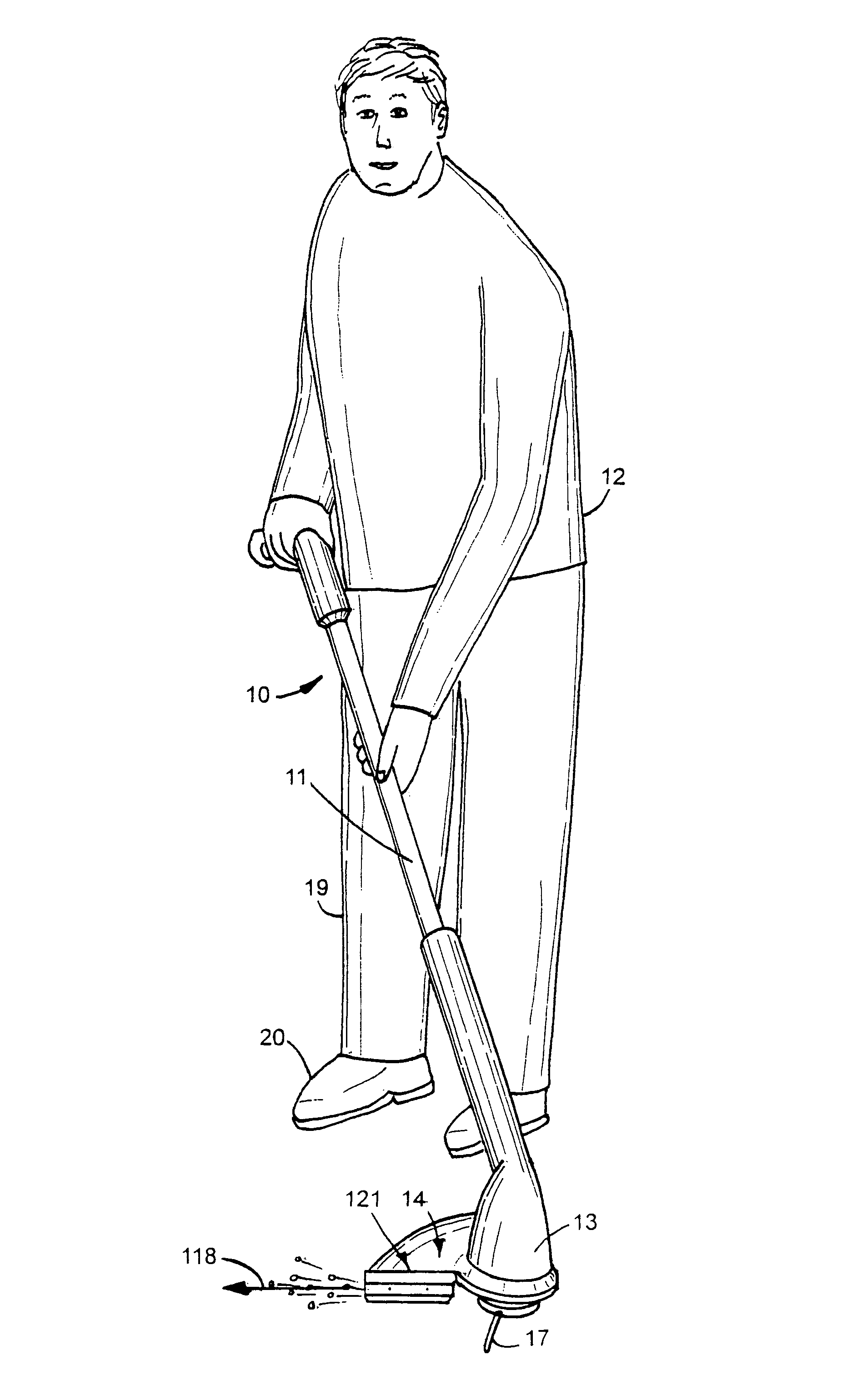
[0037]the knife and deflector apparatus 121, shown in FIGS. 11 to 21, mounted on a shroud 14 of a string trimmer 10 in use directs cut debris 118 away from legs 19 and feet 20 of workperson 12. Apparatus 121 has a knife member 122 having a front linear radial knife edge 129. The inner end of knife member 122 has an upwardly turned ear 131 that deflects cord 17 away from knife edge 129. A back wall 127 joins knife member 122 to a front wall of deflector 123. Knife and deflector apparatus 121 is a one-piece metal member attached to a front wall 126 of shroud 14 with fasteners 128, shown as nut and bolt assemblies. Knife member 122, as seen in FIGS. 13, 18, 19 and 21, extends downwardly and forwardly locating knife edge below the bottom horizontal plane of a shroud 14. Knife member 122 is inclined 15 to 20 degrees downwardly and forwardly of the front of shroud 14. Front wall 123 has a continuous flat face that directs cut debris laterally away from shroud 14 and workperson 12. Front w...
third embodiment
[0039]the knife and deflector unit 221, shown in FIGS. 22 and 23, mounted on shroud 14 directs cut debris laterally away form shroud 14 and the workperson operating the string trimmer. Knife and deflector apparatus 221 is a one-piece metal member with a horizontal knife 222 having a radial cutting edge 223 located below shroud 14 and above the circular path of moving cord 17. Cord 17 operates to move vegetation, including grass, weeds, hay and plants, into contact with edge 223 and cutting the vegetation into cut debris. A radial deflector 224 extended upwardly from shroud 14 has a generally flat front surface or face that directs air and cut debris laterally away from shroud 14 and the workperson operating the string trimmer. A horizontal support member 227 and a downwardly directed member 228 joins knife 222 to deflector 224. Member 228 has a generally flat radial surface or face that also directs air and cut debris laterally away from shroud 14. Knife and deflector apparatus 221 ...
PUM
 Abstract
Description
Claims
Application Information