Fluid purification using hydraulic vortex system

a technology of hydraulic vortex and hydraulic pressure, which is applied in the direction of vortex flow apparatus, separation process, filtration separation, etc., can solve the problems of expensive process in the desalination system, and achieve the effect of enhancing the deflection of the fluid and the subsequent generation of mini-vortices

Inactive Publication Date: 2014-01-07
GONINAN BRIEN EDWARD
View PDF15 Cites 6 Cited by
  • Summary
  • Abstract
  • Description
  • Claims
  • Application Information

AI Technical Summary

Benefits of technology

[0015]In addition, the invention provides improved decontamination through control of velocity of a water stream and with efficiency that exceeds that provided by existing gravitational, sub-surface, stormwater treatment systems.
[0016]According to the invention vortices are created in a fluid stream introduced into one or more vessels disposed in series each capable of decontamination in its own right. The vortices are created by interaction between water introduced into the vessel at a predetermined velocity, in a predetermined attitude and at least one formation in a wall of the one or more vessels. The introduced fluids in which a vortex is introduced in and prior to introduction into the vessels, which are preferably cylindrical, are dramatically spiralled and aerated causing increased cavitation and dissociation while producing a highly hostile environment for bacteria and micro organisms in the fluid's vortices.
[0017]The invention allows the reuse of effluent water, by treatment of such effluent in the process of the present invention. The invention has valuable applications to the pre-treatment of sea water or brackish water dramatically reducing the energy required for conventional desalination methods such as reverse osmosis so that the cost of desalination becomes more economical. The invention may also be used to eliminate hardness and heavy metals in bore water and particulates in stock water and irrigation. The invention further provides means to eliminate or substantially reduce chemical pollution of water reticulating systems and water recovery programs. The invention employs vortices to obtain more efficient elimination of pathogens; particulates; and various polluting substances in comparison to known system which employ vortices.
[0018]In its broadest form the present invention comprises:
[0019]an apparatus for the purification treatment of a water stream;
[0021]a vessel having a wall defining an internal space, an inlet for introducing a fluid stream into the vessel in a predetermined attitude and at a flow rate which induces a primary vortex spiral in the fluid in the vessel,

Problems solved by technology

At present desalination systems rely on expensive processes including such processes as reverse osmosis and those using chemicals.

Method used


Image

  • Fluid purification using hydraulic vortex system
  • Fluid purification using hydraulic vortex system
  • Fluid purification using hydraulic vortex system

Examples


Embodiment Construction

[0042]The invention will be described with reference to an individual assembly and to a series assembly created from a set of vessels in series.

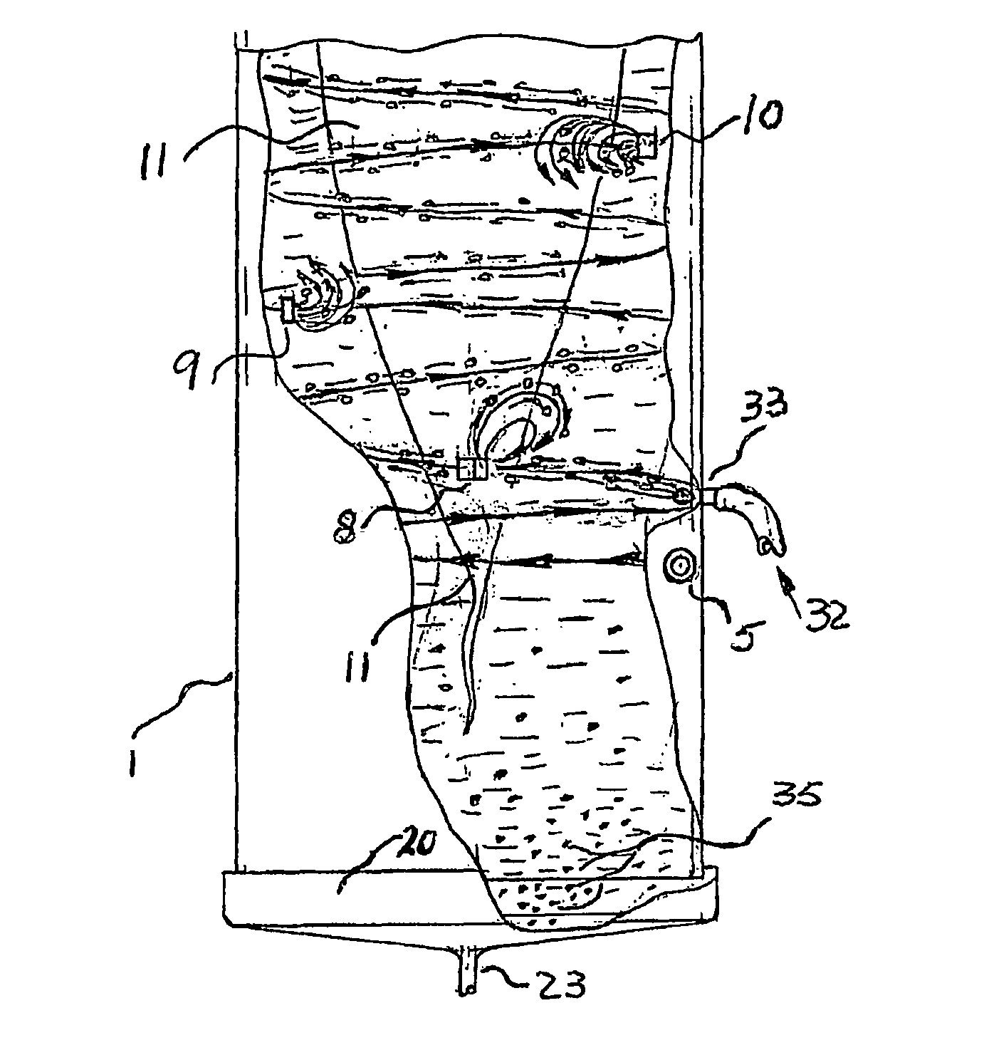
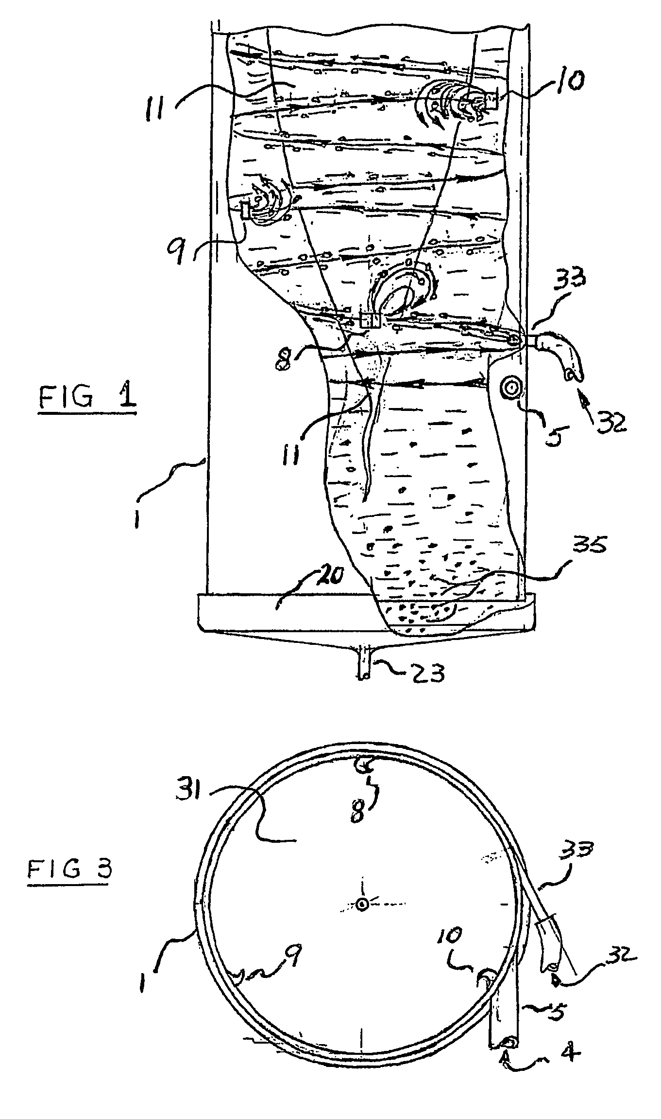
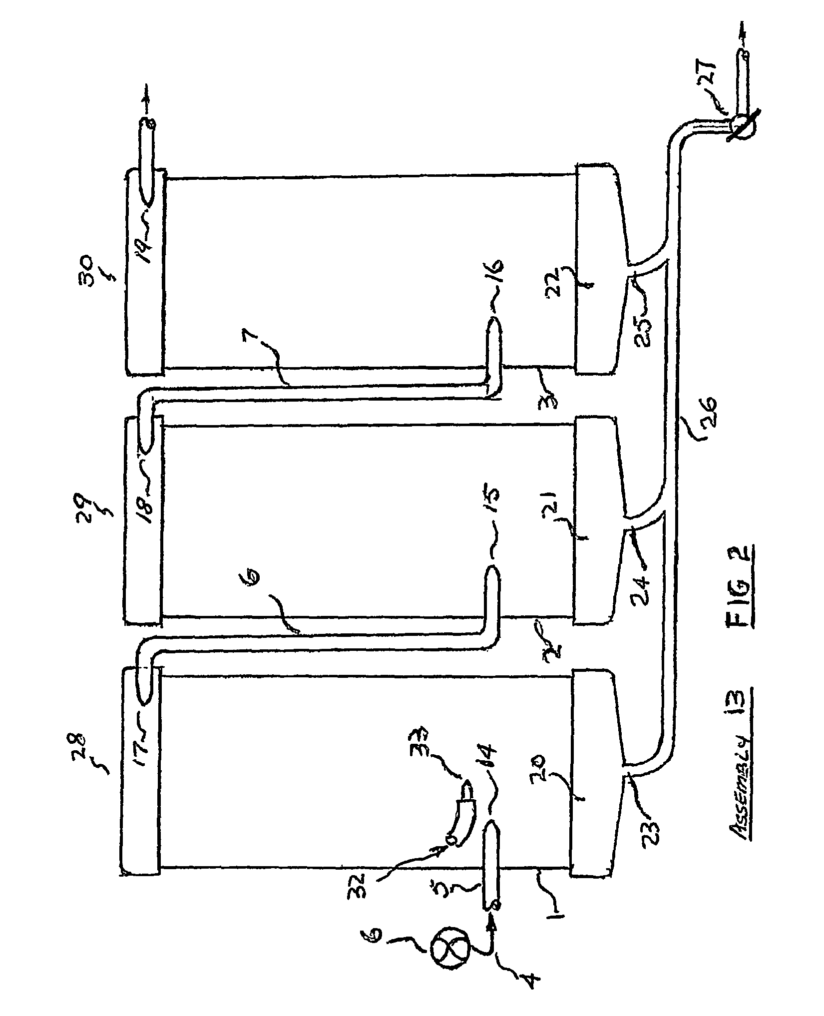
[0043]FIG. 1 shows an elevation cut away view of an assembly comprising a vortex generating vessel 1. This is a fundamental form of the invention and it will be appreciated that the invention can be configured as a series of like vessels (see FIG. 2) which decontaminate a fluid introduced into the vessels. The additional vessels either decontaminate the fluid separately or cumulatively. As shown in FIG. 3, vessel 1 has internal space 31 in which a fluid 4 is introduced via an inlet 5. Fluid 4 is introduced via inlet 5 under the action of a pump 6 (see FIG. 2). Fluid 4 may be accelerated into inlet 5 by means of a mechanical spiral (see FIG. 4) which accelerates the fluid 4 rotationally. This induces a vortex upon entry into the vessel 1. When a fluid stream 4 is introduced into the vessel, the fluid impacts on formations 8, 9, and 10 (see FI...


PUM

PropertyMeasurementUnit
diameteraaaaaaaaaa
diameteraaaaaaaaaa
velocityaaaaaaaaaa

Abstract

An assembly for water purification comprising a series of vessels which allows fluid to communicate therebetween via fluid supply lines. The assembly is arranged so as to generate a plurality of co operating vortices generated by fluid impact on formations disposed on an inner surface of the vessels to cause an ascending fluid flow to be deflected back in the direction of fluid flow thereby creating local vortices. Water exiting said vessels has higher purity than water entering the vessel.

Description

CROSS-REFERENCE TO REALTED APPLICATION[0001]This is the National Stage of International application Ser. No. PCT / AU2007 / 000565, filed May 2, 2007.[0002]The present invention relates to improvements in the efficiency of pre-treatments for fluids and more particularly relates to hydraulic vortex systems for treating contaminated fluids such as but not limited to water. The present invention also relates to vortex systems for pre treating sea water for desalination, softening of brackish water, and purification of fluids generally. The invention further provides an apparatus for such pre treatments.PRIOR ART[0003]There are in existence a wide variety of decontamination processes particularly in water treatment. These take many forms and may be used in the food industry, in sewerage treatment and in desalination.[0004]At present desalination systems rely on expensive processes including such processes as reverse osmosis and those using chemicals. In reverse osmosis, filter elements are ...

Claims


Application Information

Patent Timeline
Patent Type & Authority Patents(United States)
IPC IPC(8): C02F1/38B04C3/00
CPCC02F2301/024C02F2301/026B04C2009/008B01D21/26B04C5/26C02F1/005B04C5/04C02F1/006B04C9/00B04C5/103
Inventor GONINAN, BRIEN, EDWARD
Owner GONINAN BRIEN EDWARD
Why Eureka
Try Eureka