Method for enlarging a jaw bone using a hollow dental implant having a side perforation

a dental implant and side perforation technology, which is applied in the field of enlarging a jaw bone using a hollow dental implant having a side perforation, can solve the problems of inability to receive bridges, implants or even dentures, and the type of operation has had drawbacks, so as to avoid puncture and leakage, improve stabilization, and avoid the effect of slipping

Inactive Publication Date: 2014-01-07
KARMON BEN ZION
View PDF89 Cites 20 Cited by
  • Summary
  • Abstract
  • Description
  • Claims
  • Application Information

AI Technical Summary

Benefits of technology

[0020]The basic principle is to create a cavity into which tissue from a controlled direction is growing inside the cavity or to insert inside the body a biocompatible material to a predetermined location in a predetermined geometry and to allow contact between the tissue and the biocompatible material which preferably is bioactive. The filling material preferably is highly viscous, particulated or becomes rigid inside the body. The fact that there are holes of several dozens or several hundreds of microns allows the material to pass and to touch the surrounding tissue and to create one high viscous or rigid substance connecting the internal space created by the device and the tissue. This feature distinguishes the present invention from other inflatable devices that prevent direct contact between the internal space and the external space. There are devices that permit drug delivery through the envelop of the inflatable device but there is no inflatable device like the present devices that allow the immediate formation of a continuous mass of materials extending from the inside of the device to the tissue.
[0024]The device and method are particularly useful for plastic surgery, dental implantology, orthopedics and in cardiac surgery. In plastic surgery it can be used for soft tissue enlargement like lips and breasts and for facial bones enlargement. In dental implantology it can be used for horizontal and vertical augmentation of the alveolar ridge when the pouch is placed beneath the periosteum and for sinus augmentation when the pouch is placed beneath the Schneiderian membrane preceding the placement of dental implants. In orthopedics for fixating fractures and for minimal invasive delivering of bone regenerating materials to the gap between bone fragments.
[0084]According to a further feature of the present invention the insertion of the biocompatible filling material is expanding the expandable element.
[0141]According to a further feature of the present invention the expandable element is configured to take a specific shape as the expandable element is filled and to prevent changes in the shape of the expandable element as a result of forces coming from outside the expandable element.

Problems solved by technology

The absence of just one tooth can cause modifications throughout the dental arch and even prompt a possible softening (loss of insertion) which may cause the loss of other teeth.
Bone loss may finally modify the patient's appearance and, depending on the loss, may make him incapable of receiving bridges, implants or even dentures.
Although these methods of surgical reconstruction have been successfully performed, this type of operation has had drawbacks.
This surgical operation has had drawbacks because it is difficult to stretch and cover the augmented ridge resulting in high prevalence of membrane exposure and infection.
Unfortunately, such leakage is known to occur in spite of these precautions.
Since such leakage may cause serious injury, including paralysis, an improved device and method is needed.
Unfortunately, the bag used by Scribner may be ruptured during expansion to compact cancellous bone due to sharp projections found within the cavity to be expanded.
Filling the cavity eventually formed could allow leakage of bone cement out of the bone against vessels or nerves which may cause undesirable complications.

Method used


Image

  • Method for enlarging a jaw bone using a hollow dental implant having a side perforation
  • Method for enlarging a jaw bone using a hollow dental implant having a side perforation
  • Method for enlarging a jaw bone using a hollow dental implant having a side perforation

Examples


Embodiment Construction

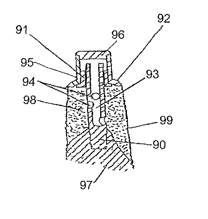
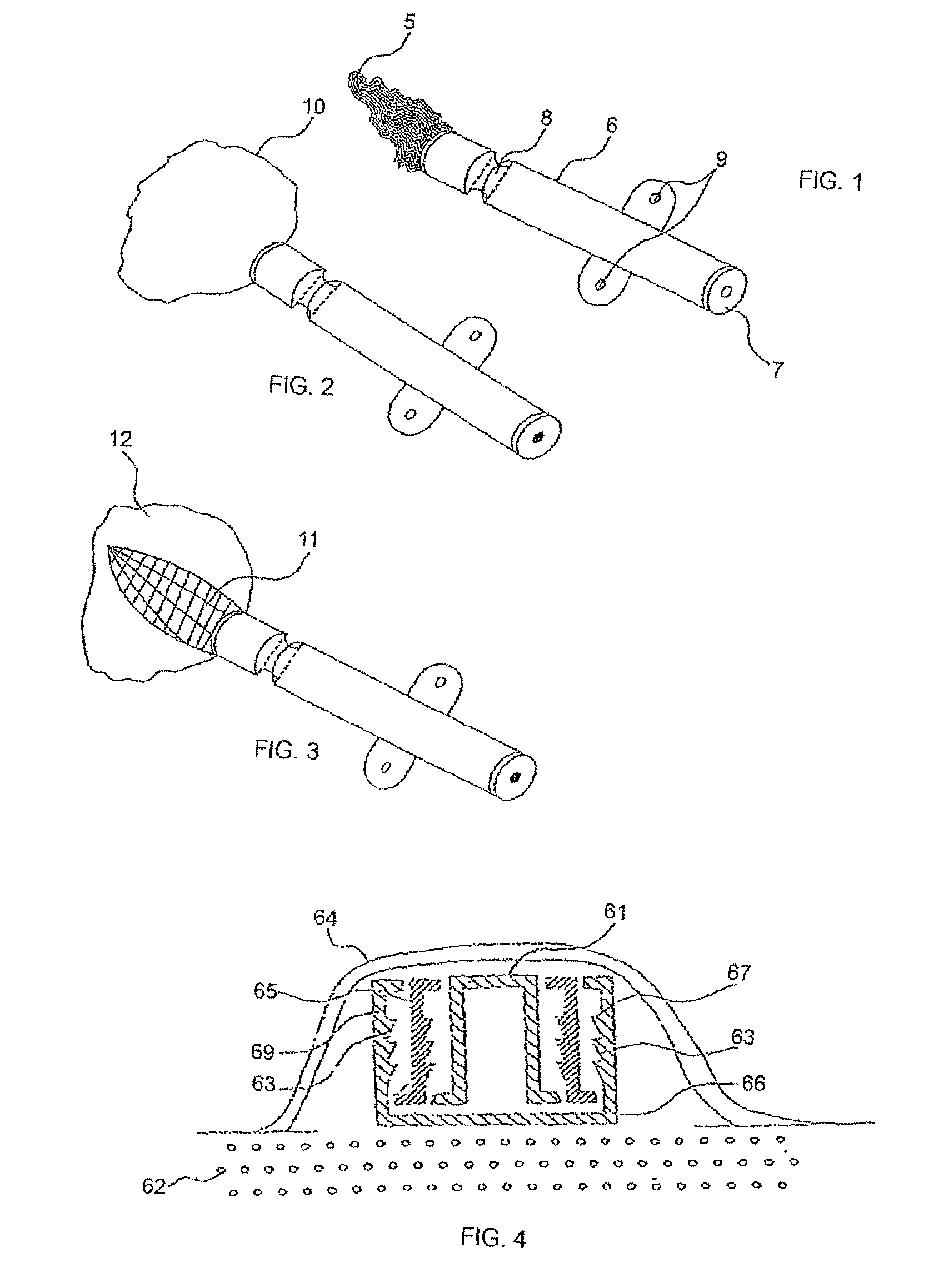
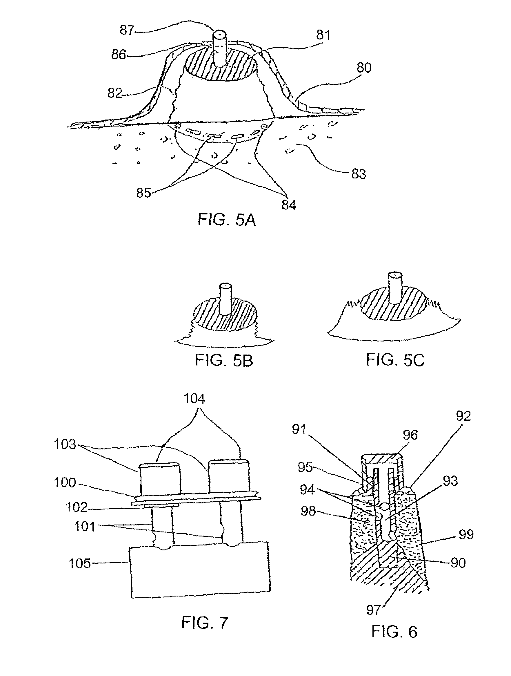
[0229]As mentioned further above there are many implementations of the invention in different tissues and organs. The following description will focus on embodiments in two fields in order to understand the principles of the device and method. The first is bone augmentation in the jaws the second is fixating bone fragments. The same principles should be used in other tissues and organs.

[0230]Before turning to the features of the present invention in more detail, it will be useful to clarify certain terminology as will be used herein in the description and claims. Specifically, it should be noted that the present invention is useful in a wide range of applications in which living tissue is to be expanded, stretched, fixated or displaced. The term “living tissue” is used herein to refer to any living tissue including, but not limited to, an organ, tube, vessel, cavity, bone cavity or membrane, and interfaces between any two or more of the above. Where used within a single type of tiss...


PUM

PropertyMeasurementUnit
widthaaaaaaaaaa
heightaaaaaaaaaa
depthaaaaaaaaaa

Abstract

A method for inserting a flowable material adjacent the alveolar ridge bone through an elongated tube having an a side perforation. The elongated tube can be a dental implant.

Description

[0001]This patent application is a U.S. Continuation in Part application of Ser. No. 11 / 126,208 filed on May 11, 2005, for which U.S. Pat. No. 7,749,267 was issued on Apr. 7, 2010 and which is a Continuation in Part of PCT / IL2003 / 00951 filed Nov. 12, 2003, expired, which is a Continuation in Part of U.S. patent application Ser. No. 10 / 291,477 filed Nov. 12, 2002, abandoned, which is a Continuation in Part of PCT / IL2001 / 00408 filed May 9, 2001, expired, the contents of which are incorporated herein by reference.FIELD AND BACKGROUND OF THE INVENTION[0002]The present invention relates to an improved methods and devices for treating and healing a tissue deficiency or pathology in a living human or animal body. The methods and the devices combine a mechanical action and a biological action.[0003]For example, the present invention can be used for guided bone regeneration in the jaws as part of dental treatment with dental implants. It can be used to fixate bones, to fill bone cavities and...

Claims


Application Information

Patent Timeline
Patent Type & Authority Patents(United States)
IPC IPC(8): A61C8/00
CPCA61F2002/3631A61B17/7258A61B2017/00557A61B17/8802A61F2/44A61F2002/30932A61B17/742A61B17/025A61F2002/30738A61B17/68A61F2/30734A61F2002/30062A61F2210/0004A61F2002/30919A61C8/0009A61F2/30723A61F2002/2832A61B17/58A61F2250/0098A61F2002/2828A61B17/666A61B17/8822A61C8/0006A61F2002/4631A61F2002/30581A61F2/36A61F2/3676A61F2002/3008A61B17/7098A61F2/3662A61B2017/0256A61F2/4601A61B19/24A61B2017/00004A61C8/0092A61F2250/0018A61F2/30724A61B17/7061A61F2002/30014A61B19/54A61B17/72A61C8/0013A61C8/0022A61B90/02A61B90/39A61B2090/3966A61C8/0039
Inventor KARMON, BEN-ZION
Owner KARMON BEN ZION
Why Eureka
Try Eureka