
Tri-directional articulating catheter

a catheter and articulation technology, applied in catheters, other medical devices, medical devices, etc., can solve the problems of compromising the safety of the central lumen, and achieve the effect of resisting the central working lumen, facilitating the distal tip articulation, and avoiding the risk of central lumen compression

Active Publication Date: 2007-11-29
TAHERI LADUCA
View PDF14 Cites 57 Cited by
  • Summary
  • Abstract
  • Description
  • Claims
  • Application Information

AI Technical Summary

Benefits of technology

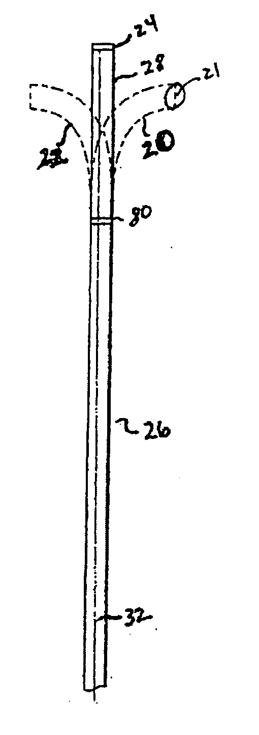
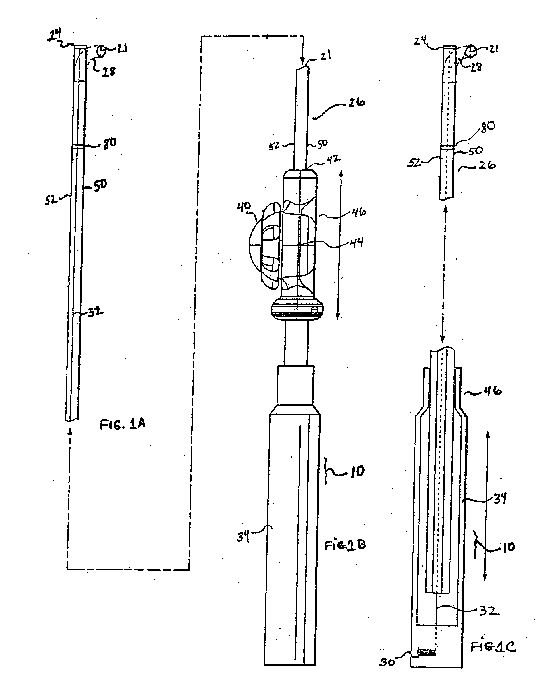
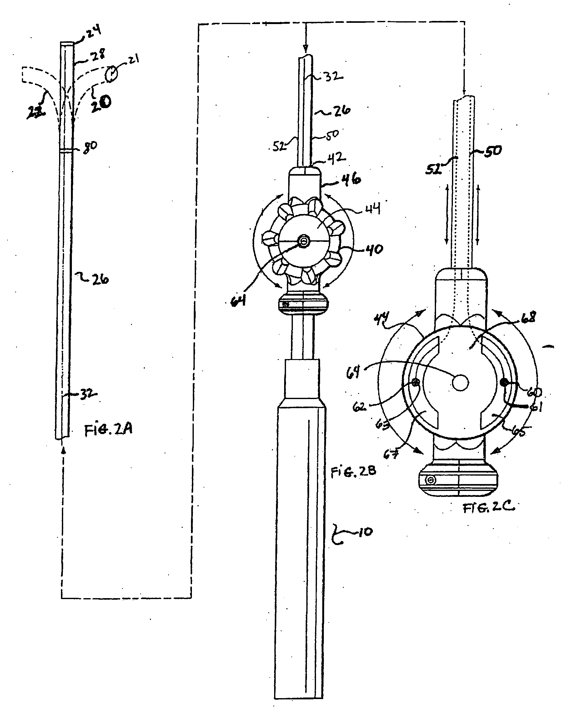
[0010] The invention is a catheter with a central working lumen that provides bi- and tri-directional articulation at the distal tip while also being capable of resisting compression of the central working lumen. The central working lumen may thus be accessed during the procedure by one or more instruments because it has not compressed. The instruments are needed to perform particular given functions that support the procedure as a whole. A risk of compression in the central working lumen occurs when selective tension is applied on steering wires that are attached to the distal tip of the catheter. The tension facilitates the distal tip articulation but also risks compression of the central lumen. In the invention, the distal tip of the catheter remains flexible enough to bend in response to selective tension placed on the steering wires and at the same time the central lumen resists compression due to the gradually increased strength of the elongate catheter body as it moves proximally from the distal tip. In other words, the catheter is designed to be most flexible at the tip, and as you move proximally from the tip, the flexibility of the catheter decreases, while the wall strength increases. Accordingly, the distal tip is able to respond to steering signals that bend the tip without causing the central working lumen to compress.
[0013] A donut balloon embodiment to these catheters facilitates fluid occlusion in a lumen with fluid flow while a procedure is underway. The donut balloon also provides access through one or more peripheral lumens to the site through the balloon, thereby avoiding direct contact with tissue or blood where such contact is not necessary or beneficial to the function of the accessing instruments.

Problems solved by technology

A risk of compression in the central working lumen occurs when selective tension is applied on steering wires that are attached to the distal tip of the catheter.
The tension facilitates the distal tip articulation but also risks compression of the central lumen.

Method used


Image

  • Tri-directional articulating catheter
  • Tri-directional articulating catheter
  • Tri-directional articulating catheter

Examples


Embodiment Construction

[0016] One embodiment of the invention is a catheter having an elongate catheter body configured so that the distal tip can articulate in two opposite directions along a plane of articulation without compression of the central working lumen. The articulation is accomplished by steering two wires that are placed within opposed peripheral lumens that themselves are disposed on an exterior surface of a central working lumen. The positioning of the opposed peripheral lumens creates the plane of articulation. The placement of the steering wires in peripheral lumens exterior to the central working lumen provides resistance to compression at the distal tip along the length of a bend that occurs when selective tension is applied to one wire.

[0017] The material that constitutes the distal tip is composed of combinations of materials in order to provide maximum flexibility at the very tip and increasing strength (and so reduced flexibility and reduced tendency for compression) in the materia...


PUM


Abstract

A catheter capable of articulating in two and three directions is provided. Articulation at the distal tip of the catheter is facilitated by applying selective tension on a steering wire disposed in a lumen that resides peripheral to a central working lumen. Tension on the steering wire through the peripheral lumen causes the catheter tip to bend while the central working lumen resists compression.

Description

CROSS-REFERENCE TO RELATED APPLICATIONS [0001] This application claims the benefit of U.S. Provisional Application No. 60 / 749,731 filed Dec. 12, 2005 which is incorporated herein by reference in its entirety.FIELD [0002] The present invention relates generally to the field of steerable catheters having the ability to articulate in two or three directions. BACKGROUND OF THE INVENTION [0003] With the popularity of minimally invasive medical procedures, catheter designers continue to revise and improve catheters for medical use, trying to build catheters that can articulate in mammalian subjects and perform the challenging functions demanded of minimally invasive procedures. Catheters for minimally invasive procedures need to bend at the distal tip and need to allow access through the catheter-body by instruments that perform the procedure. Catheters with steerable wires and proximal controls have been built and described. The challenge continues with these catheters to build a device ...

Claims


Application Information

Patent Timeline
IPC IPC(8): A61M25/092
CPCA61M25/0147A61M25/008
Inventor LADUCA, ROBERT C.LADUCA, PAUL A.
Owner TAHERI LADUCA
Learn More