Protected coaxial cable

a coaxial cable and shielding technology, applied in the direction of power cables, cables, coupling device connections, etc., can solve the problems of wireless solutions that cannot solve the problem of permanent alteration of buildings, unauthorized building modifications, and ownership of cable modifications,

Active Publication Date: 2011-07-14
HOLLAND ELECTRONICS
View PDF11 Cites 9 Cited by
  • Summary
  • Abstract
  • Description
  • Claims
  • Application Information

AI Technical Summary

Benefits of technology

[0025]And, in yet another embodiment, a cable assembly includes an elongated member including two flanges and a cross-member; the flanges extend from opposed sides of the cross-member and form first and second elongated pockets; a micro-coaxial cable is positioned at least partially within and extending along a length of the first pocket; and, the flanges, cross-member, and micro-coaxial cable are flexible and in combination operative to enable the cable assembly to substantially retain deformation consistent with bending the cable assembly around obstructions.

Problems solved by technology

But, drilling a hole in a wall and routing a cable through the hole makes a permanent alteration to the building.
Since most MDU occupants do now own the premises, this simple action raises issues including unauthorized building modifications, ownership of cable modifications, liability for changes, and liability for related safety issues.
Wireless solutions do not solve this problem.
While capacitive coupling solves the problem of transporting high frequency signals across a glass boundary, such wireless solutions are unable to transport mid and low frequency signals.
But, using such openings to pass a typical 7 mm O.D. coaxial cable presents challenges including; closing the window or door when it is blocked by the cable; and, maintaining a fully functional cable when it is deformed by impact and compression from operation of the window or door.
Therefore, a 7 mm coaxial cable in this application will likely be squeezed and damaged while a cable of 3 mm or smaller diameter will likely avoid damage.
Coaxial cable deformations are undesirable because they damage cable covering and abruptly change the coaxial cable conductor spacing.
In particular, conductor spacing changes tend to alter the characteristic impedance of the cable and reflect radio frequency power back toward the source, causing a condition called standing waves.
An abrupt change in impedance acts as a signal bottleneck and may result in detrimental data delays and signal lock-ups found in satellite TV signal transmission systems.
None of these methods provides a robust solution.
The first method often fails to protect the cable since cables over 3 mm in diameter are larger than typically available window / door to frame gaps.
When the door or window is closed, these cables are deformed to varying degrees rendering them useless and / or degrading their RF performance.
In addition, the outer covering on such cables is soft and easily breached by repeated operation of windows / doors.
Here, the minimum bending radius of the extender cable is unacceptably increased by the armor.
The third method using a flattened / non-circular coaxial cable provides inferior RF performance even before it is installed.
In addition, bending the flat coaxial cable to accommodate one or more sharp bends of window / door frames further distorts the cable cross-section and impairs signal transmission.
Further, the soft sheath of a coaxial cable can easily be breached by repetitive impacts from operation of windows / doors.

Method used


Image

  • Protected coaxial cable
  • Protected coaxial cable
  • Protected coaxial cable

Examples


Embodiment Construction

[0041]The disclosure provided in the following pages describes examples of some embodiments of the invention. The designs, figures, and description are non-limiting examples of embodiments they disclose. For example, other embodiments of the disclosed device and / or method may or may not include the features described herein. Moreover, disclosed advantages and benefits may apply to only certain embodiments of the invention and should not be used to limit the disclosed invention.

[0042]To the extent parts, components and functions of the described invention exchange electric power or signals, the associated interconnections and couplings may be direct or indirect unless explicitly described as being limited to one or the other. Notably, parts that are connected or coupled may be indirectly connected and may have other devices interposed therebetween including devices known to persons of ordinary skill in the art.

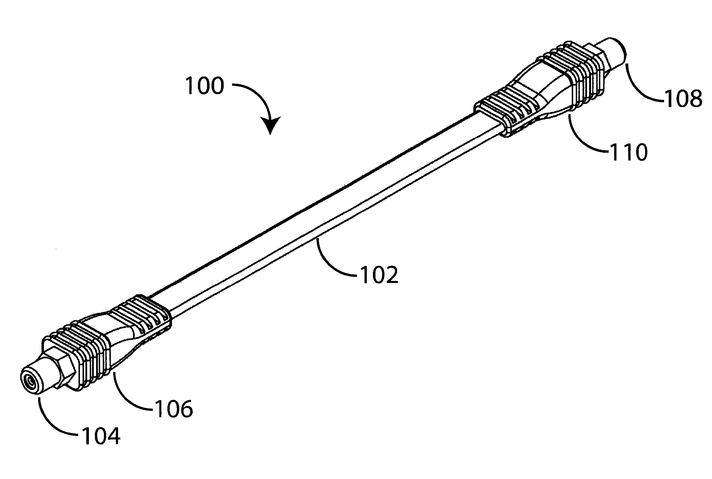
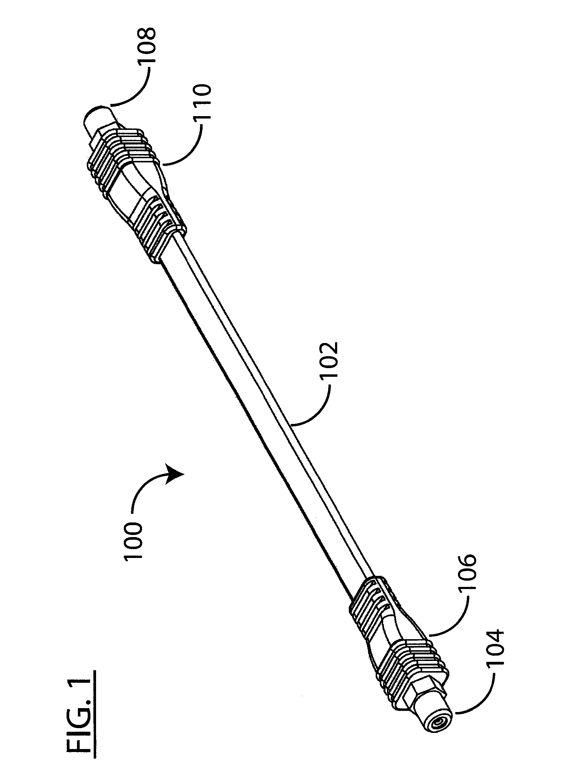
[0043]FIG. 1 shows a guarded coaxial cable assembly in accordance with the...


PUM

PropertyMeasurementUnit
thicknessaaaaaaaaaa
widthaaaaaaaaaa
thicknessaaaaaaaaaa

Abstract

A guarded coaxial cable assembly includes a micro-coaxial cable and an adjacent structure for protecting the micro-coaxial cable.

Description

PRIORITY CLAIM[0001]This application is a continuation-in-part of U.S. patent application Ser. No. 12 / 634,293 filed Dec. 9, 2009.BACKGROUND OF THE INVENTION[0002]1. Field of the Invention[0003]The present invention relates to an article of manufacture for conducting electrical signals. In particular, a guarded coaxial cable is provided for conducting radio frequency signals.[0004]2. Discussion of the Related Art[0005]Coaxial cables used for television including satellite, cable TV and antenna cables are typically 7 mm in diameter, a size large enough to limit signal loss over the distances traveled from an outside location to a location inside a home or building. Usually these cables originate outside a home or apartment such as a multiple dwelling unit (MDU) and terminate inside where TV, wireless, or satellite reception equipment is located.[0006]A cable often enters a building through a hole drilled in a wall. But, drilling a hole in a wall and routing a cable through the hole ma...

Claims


Application Information

Patent Timeline
Patent Type & Authority Applications(United States)
IPC IPC(8): H01R11/00H01B7/18
CPCH01B7/0869H01R24/54H01B11/1895H01B7/1815
Inventor HOLLAND, MICHAEL
Owner HOLLAND ELECTRONICS
Why Eureka
Try Eureka