Unstressed connector position assurance device and connector assembly

a technology of position assurance device and connector, which is applied in the direction of connection, electrical apparatus, coupling device connection, etc., can solve the problems of increasing the likelihood of material creep, affecting the effective locking capability of the primary locking system of the connector, and affecting the integrity of the material, so as to reduce the stress

Active Publication Date: 2011-09-13
J S T CORP
View PDF9 Cites 99 Cited by
  • Summary
  • Abstract
  • Description
  • Claims
  • Application Information

AI Technical Summary

Benefits of technology

[0004]In general, in one or more aspects, the invention relates to a Connector Position Assurance Device (CPA) device, the use of which reduces stress on the device in both the pre-lock and final-lock positions. The CPA device includes a body portion, a first arm, and a second arm. The first arm is attached to the body portion, extended from the body portion, and includes a locking groove proximate a distal end thereof. The second arm, which includes a locking latch, is attached to the body portion, spaced apart from the first arm, and extended from the body portion. When the CPA device is guided along the female housing, the locking groove and the locking latch lock onto complementary protrusions on the female housing in a pre-lock position, only to be dislodged upon contact of a sloped surface at the distal end of the first arm with the male header connector during insertion of the male header connector into the female housing to proceed to a final-lock position.

Problems solved by technology

One conventional method employed in the art to disengage the CPA device from a pre-lock position, as described in U.S. Pat. No. 6,077,101, for example, utilizes a lock in the header side, which, if damaged, may affect the effective locking capability of the primary locking system of the connector.
Additionally, as the CPA device is in a stressed state when full mating and locking are accomplished, thermal effects under a long-term influence of high temperature conditions can increase the likelihood of material creep.
This can affect material integrity and, ultimately, the functionality of the CPA device.
However, CPA devices often require standard headers, such as headers conforming to United States Council for Automotive Research (USCAR) footprint.

Method used


Image

  • Unstressed connector position assurance device and connector assembly
  • Unstressed connector position assurance device and connector assembly
  • Unstressed connector position assurance device and connector assembly

Examples


Embodiment Construction

[0019]Specific embodiments of the invention will now be described in detail with reference to the accompanying figures. Like elements in the various figures are denoted by like reference numerals for consistency.

[0020]In the following detailed description of embodiments of the invention, numerous specific details are set forth in order to provide a more thorough understanding of the invention. However, it will be apparent to one of ordinary skill in the art that the invention may be practiced without these specific details. In other instances, well-known features have not been described in detail to avoid unnecessarily complicating the description.

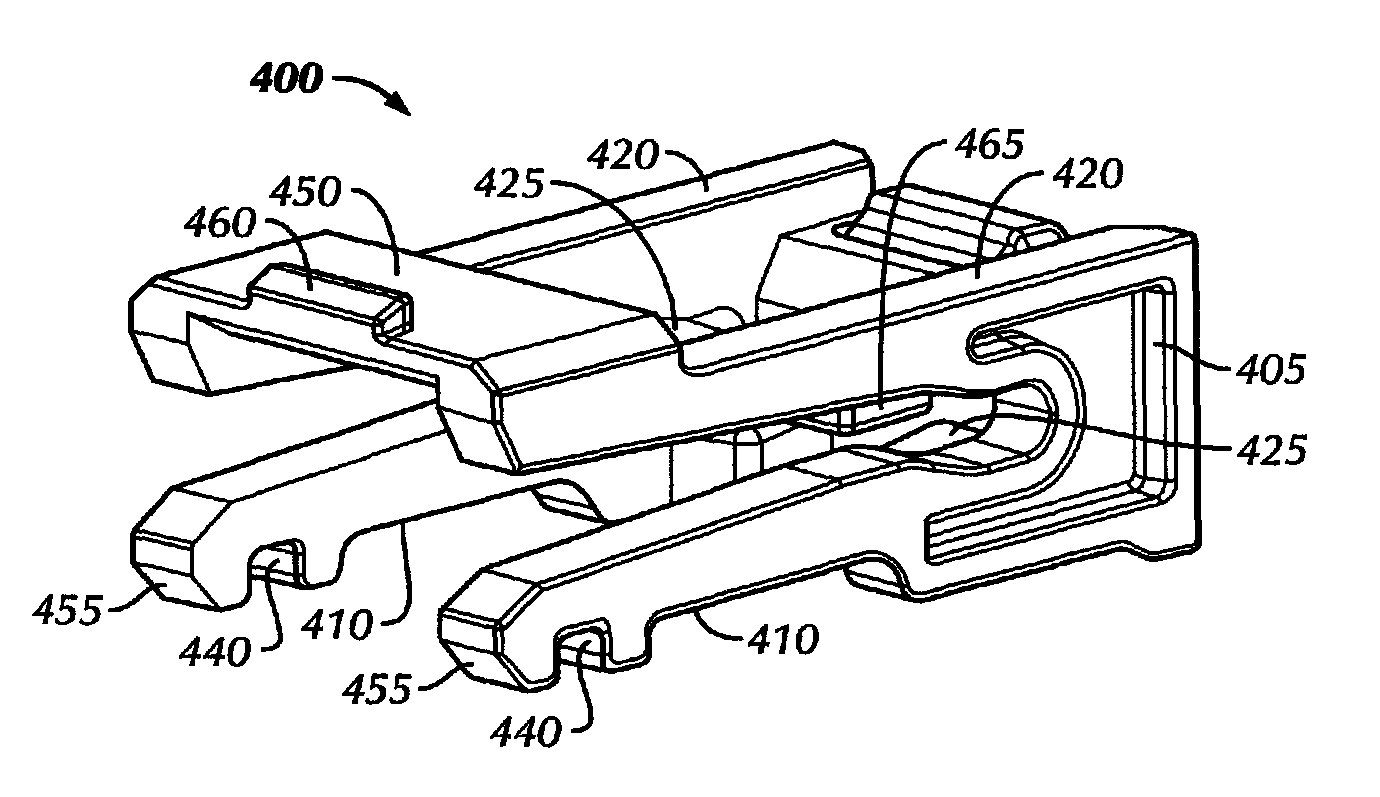
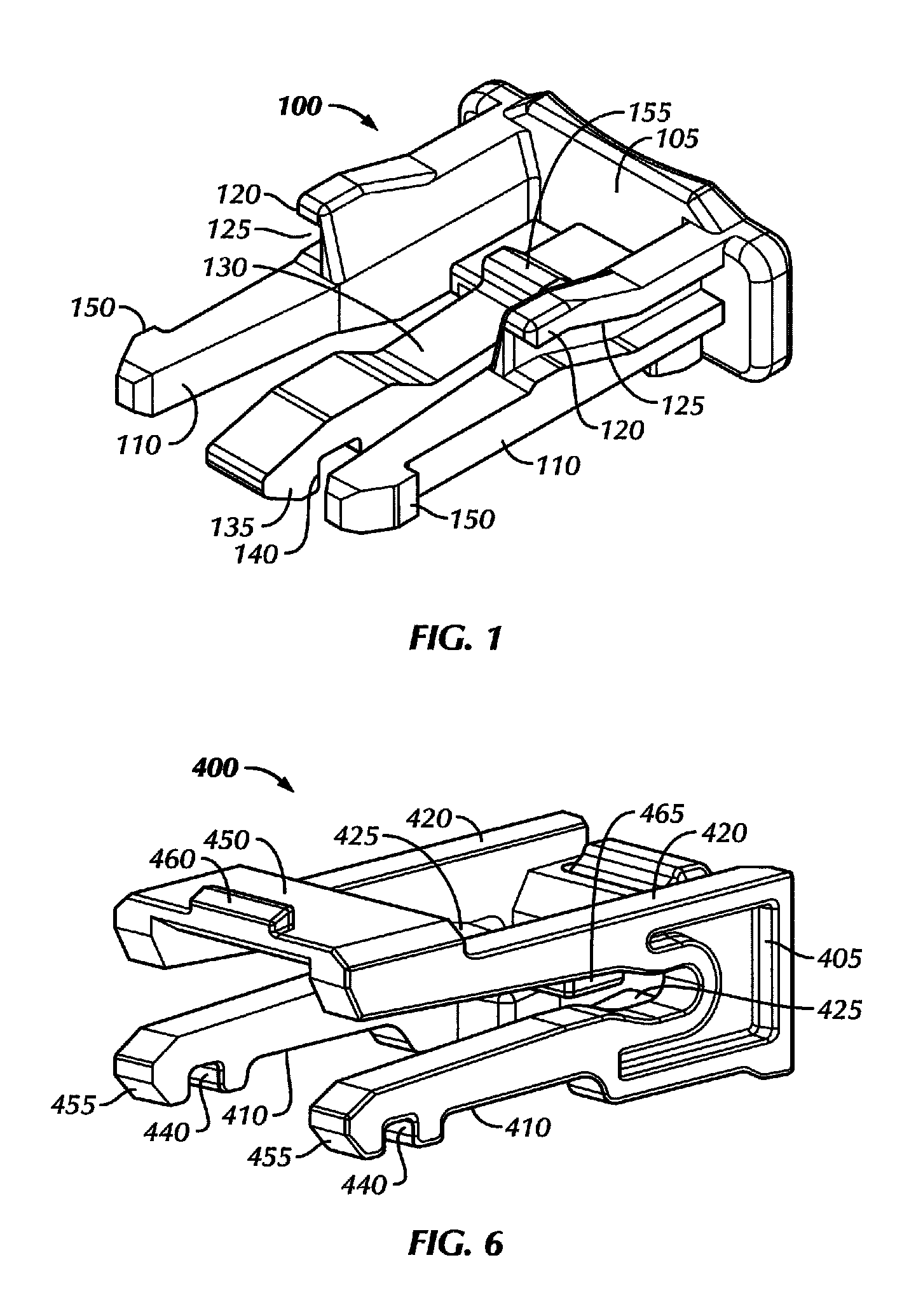
[0021]One or more embodiments of the invention overcomes deformation / stress at both pre-lock and final lock positions, without requiring header design modification. Referring to FIG. 1, in accordance with one or more embodiments of the invention, a Connector Position Assurance (CPA) device 100 comprises two parallel arms 110 spaced apart f...


PUM


Abstract

A Connector Position Assurance (CPA) device for ensuring mating of a male header connector with a female housing includes a body portion, a first arm, and a second arm. The first arm is attached to the body portion, extended from the body portion, and includes a locking groove proximate a distal end thereof. The second arm, which includes a locking latch, is spaced apart from the first arm, attached to the body portion, and extended from the body portion. When the CPA device is guided along the female housing, the locking groove and the locking latch lock onto complementary protrusions on the female housing in a pre-lock position, only to be dislodged upon contact of a sloped surface at the distal end of the first arm with the male header connector during insertion of the male header connector into the female housing to proceed to a final-lock position.

Description

BACKGROUND OF INVENTION[0001]Connector Position Assurance (CPA) devices are commonly used in electrical connectors in order to ensure that the connector bodies are properly locked and mated together. Half-mated connections can be avoided by having a pre-locking mechanism that makes it impossible for the CPA device to be pushed into a final locking state unless the electrical connectors are mated in the desired manner.[0002]One conventional method employed in the art to disengage the CPA device from a pre-lock position, as described in U.S. Pat. No. 6,077,101, for example, utilizes a lock in the header side, which, if damaged, may affect the effective locking capability of the primary locking system of the connector. Additionally, as the CPA device is in a stressed state when full mating and locking are accomplished, thermal effects under a long-term influence of high temperature conditions can increase the likelihood of material creep. This can affect material integrity and, ultimat...

Claims


Application Information

Patent Timeline
Patent Type & Authority Patents(United States)
IPC IPC(8): H01R13/627
CPCH01R13/641H01R13/6275
Inventor KWAN, MENG SANGAZAD, VIKASCHEN, PING
Owner J S T CORP
Why Eureka
Try Eureka