
Valve seat, valve with seat and method of fitting seat to valve
- Summary
- Abstract
- Description
- Claims
- Application Information
AI Technical Summary
Benefits of technology
Problems solved by technology
Method used
Image

Examples
Embodiment Construction
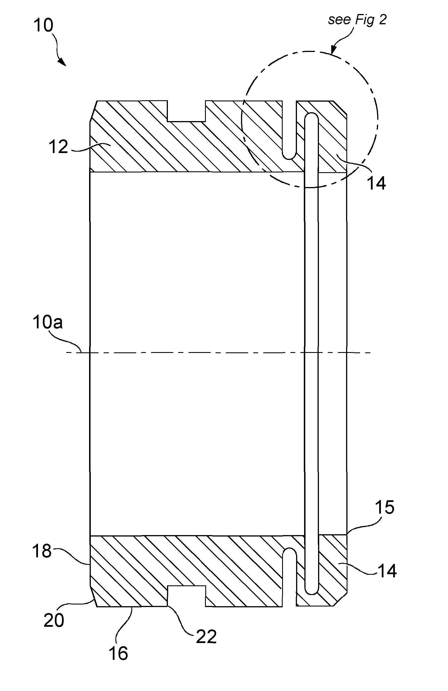
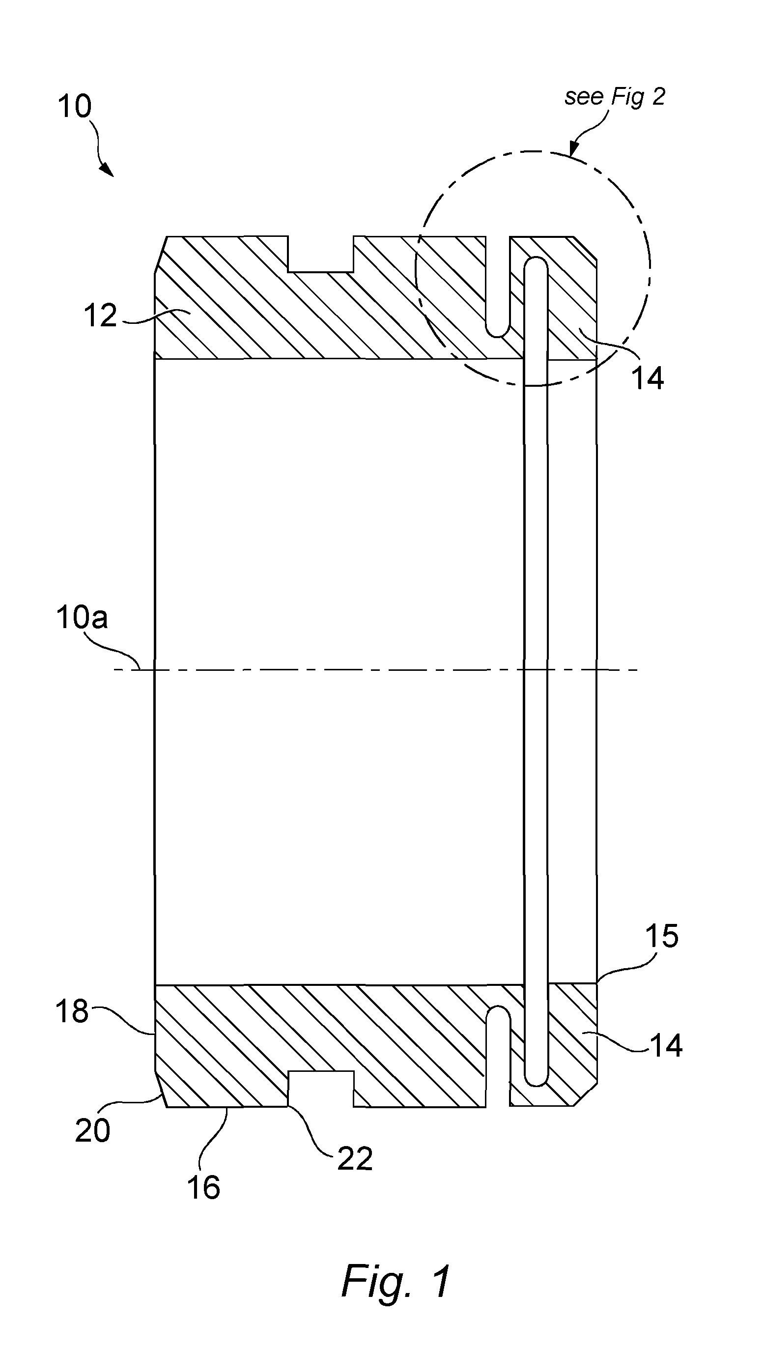
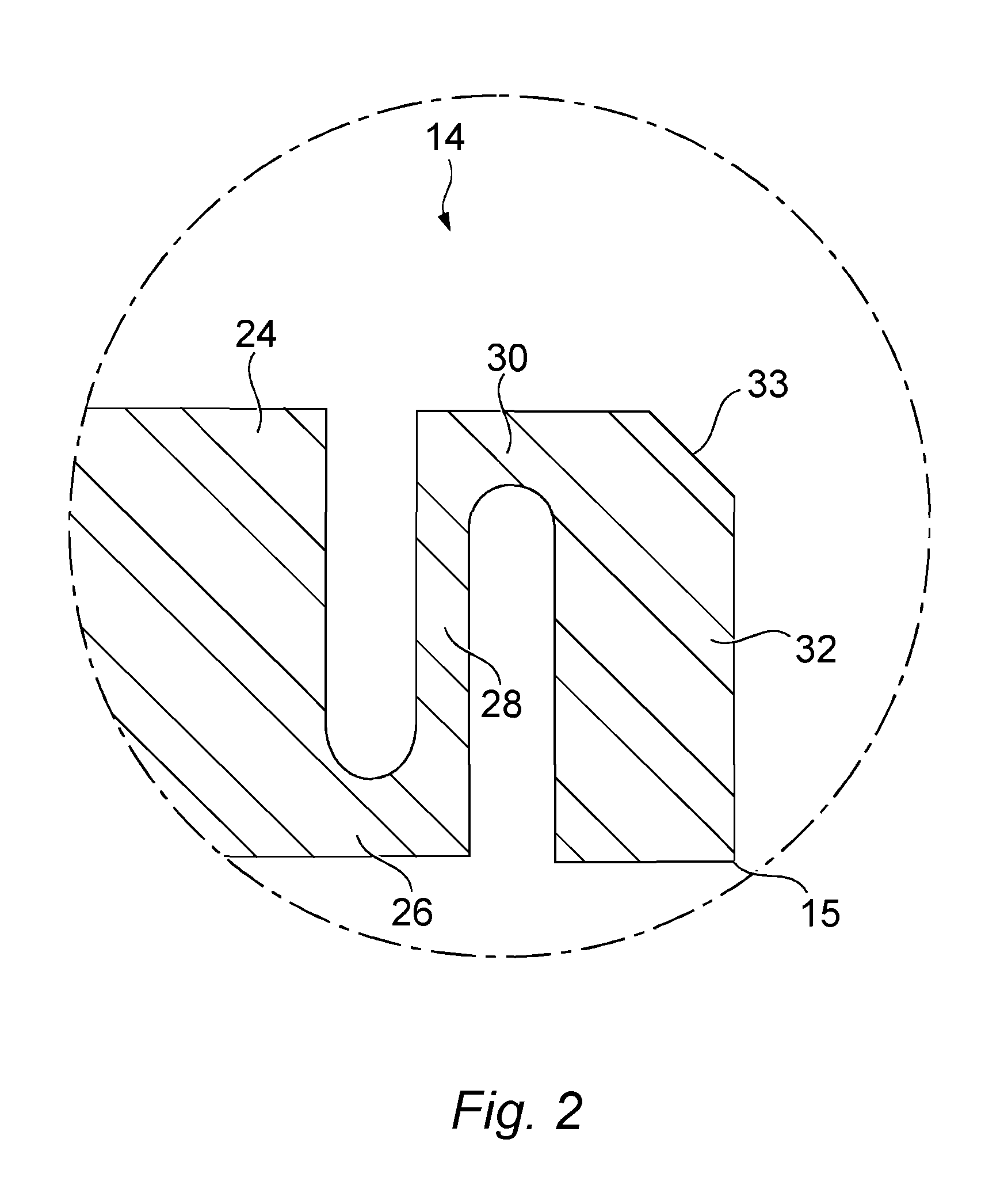
[0039]A valve seat 10 formed of metal such as stainless steel or ICONEL (Trade Mark) according to the first aspect of the present invention is shown in cross-section in FIG. 1. It comprises a valve seat body 12 and a biasing device 14. The two parts are formed integrally, in this case manufactured by forming the parts separately, before welding the valve seat body 12 permanently to the biasing device 14. Alternatively, the valve seat body 12 and the biasing device 14 can be manufactured from one piece of metal.
[0040]The valve seat body 12, and by extension the valve seat 10 itself, is generally cylindrical, and includes an outer sidewall 16 and a front end face 18. The sidewall 16 and end face 18 are connected via a chamfered shoulder 20. Disposed approximately half-way along the sidewall 16 is a circumferential groove 22, which extends around the exterior surface of the valve seat 10, and disposed in a plane perpendicular to the dominant central axis 10a of the valve seat 10.
[0041]...
PUM
 Abstract
Description
Claims
Application Information