
Saddle support structure

a support structure and saddle technology, applied in the field of saddles, can solve the problems of increasing the pressure exerted by the saddle, affecting the use of the saddle, affecting the use of the saddle, etc., and achieve the effect of high wellness and comfort during us

Inactive Publication Date: 2006-03-09
SELLE ROYAL SPA
View PDF10 Cites 10 Cited by
  • Summary
  • Abstract
  • Description
  • Claims
  • Application Information

AI Technical Summary

Benefits of technology

[0015] A main object of this invention is to obviate the above mentioned drawbacks, by providing a support structure for a bicycle or other pedal driven machine, which is adapted to fit the muscles of the legs and buttocks, and to provide high wellness and comfort during use.
[0016] A further object of the invention is to provide a support structure which has a sufficiently wide seat surface and such a shape as to limit compression both caused by the user's weight and by the pedaling motion, which are exerted in the inside thigh areas of the user.

Problems solved by technology

During pedaling, the inside thigh areas of the user repeatedly contact the side periphery of the saddle, thereby causing periodic rubbing and consequent local irritations, unless particular arrangements are provided.
This allows to reduce the contact action of the side edges of the saddle on the relevant body areas but leads to other drawbacks.
A first drawback consists in that the presence of such pliable edges reduces the surface in contact with the user's body and, as a result, increases the pressure exerted by the saddle.
A second drawback associated with such pliable side edges is that they cause the rigid structure to be permanently, and often unacceptably, weakened.
An apparent limit of this solution lies in that the additional pad, when not properly secured, may be displaced during use, due to the motion of the legs, and is in any case a supplement member, which has to be repeatedly checked for proper positioning.
Further, the use of an additional member necessarily implies a more complex construction, requires particular care in mounting operations, and greatly changes the aspect of the saddle.
A common drawback of all these embodiments consists in the remarkably complicated structure introduced by the used of these swingable fastening means, and by the consequent increase of construction costs.

Method used


Image

  • Saddle support structure
  • Saddle support structure
  • Saddle support structure

Examples


Embodiment Construction

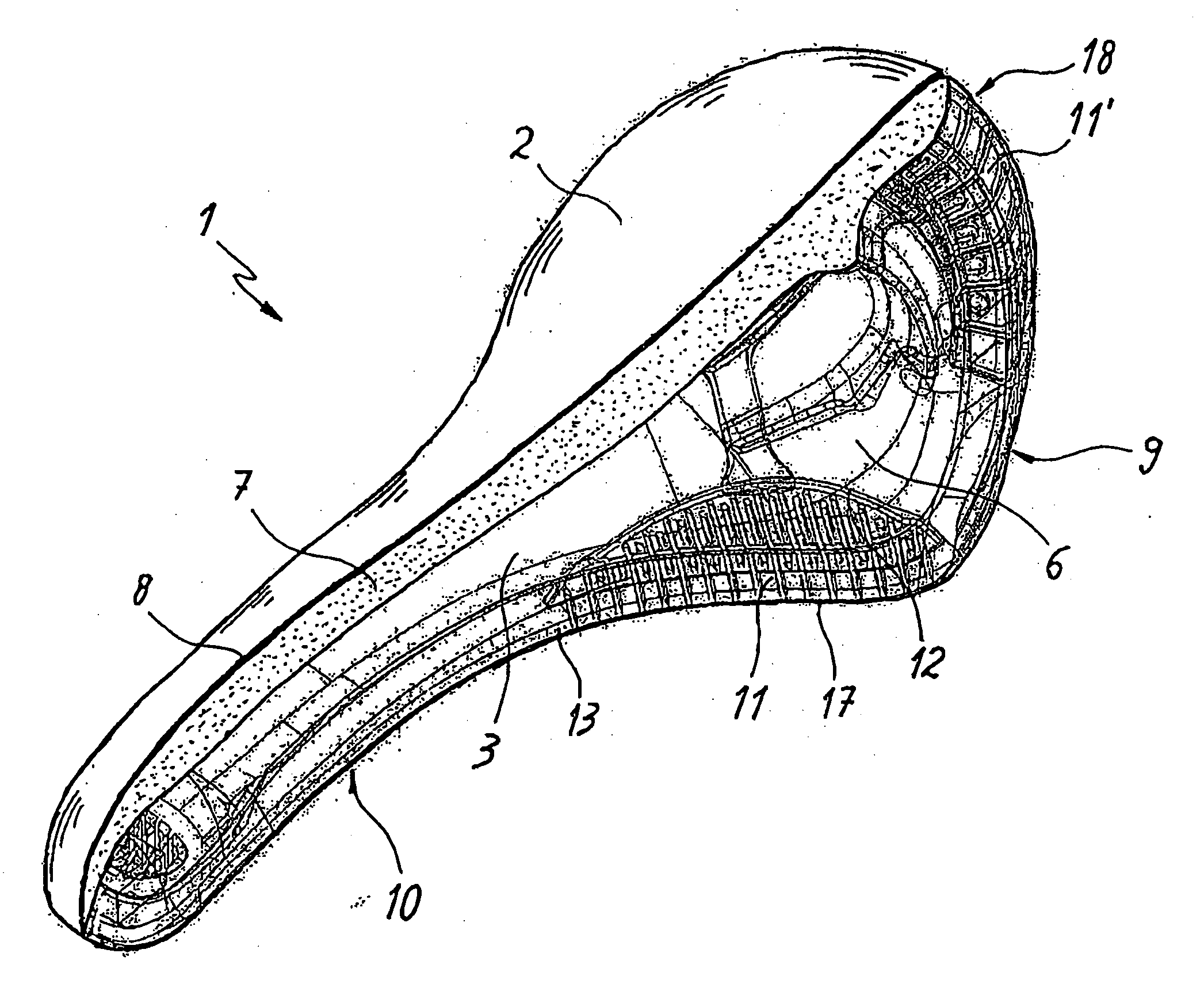
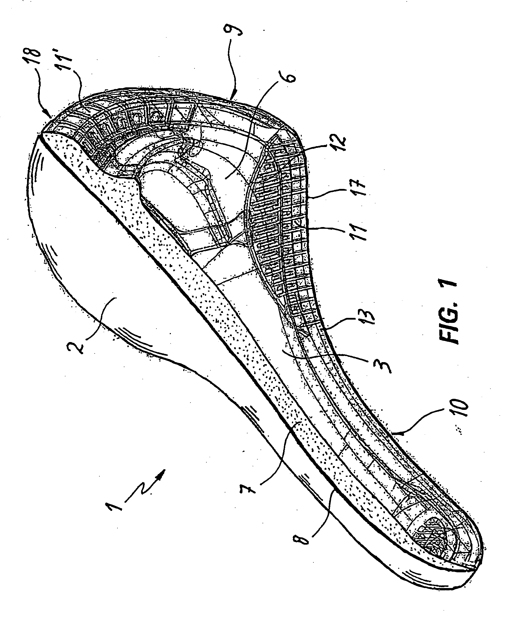
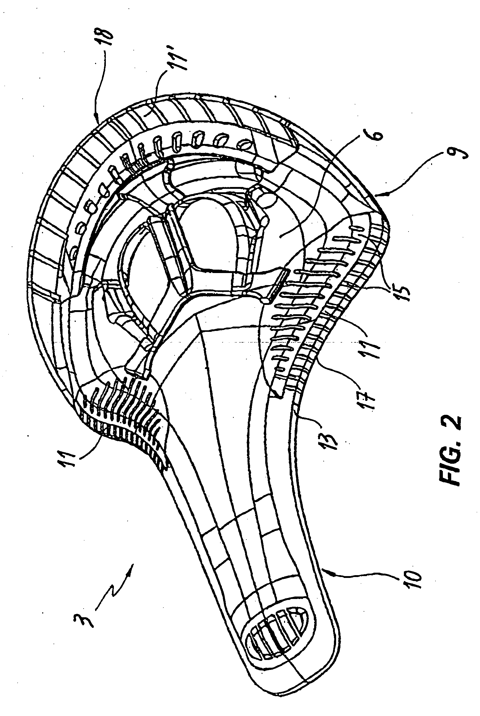
[0036] With particular reference to the above mentioned figures, a support structure or saddle 1 according to the invention is shown. The support structure 1 has a seat surface 2, and is particularly designed for bicycles or other pedal driven machines e.g., exercise bicycles and tricycles.

[0037] The support structure 1 comprises a substantially rigid or semi-rigid frame 3, which is made of plastic or composite materials. For example, the frame 3 may be made by molding or injection molding of plastic materials, such as polyethylene terephthalate (PET), polybutylene terephthalate (PBT), polyvinylchloride (PVC), or polyamide polymers, such as PA6 and PA12. Other similar polymers can also be used. Further, the plastic materials can be molded with different types of fillers. The frame 3 may be secured to a bicycle or a pedal driven machine by appropriate connection means 4, such as those generally known in the art. Such connection means 4 are placed on the bottom side 5 of the frame 3....


PUM


Abstract

A support structure having a seat surface, particularly for pedal operated machines, such as bicycles, comprises a substantially rigid or semi-rigid frame, means for connecting the frame to the pedal operated machine, a yieldable padding secured to the top face of the frame, a covering layer superimposed to the yieldable pad, wherein the frame has one or more differential rigidity portions, preferably adapted to facilitate the pedaling motion. The differential rigidity portions are preferably situated at an outer peripheral edge of the frame, along which at least one recess is provided. Each differential rigidity portion comprises a plurality of outwardly extending projections.

Description

CROSS-REFERENCE TO RELATED APPLICATIONS [0001] This is a continuation application of PCT / IB2003 / 004334, filed Oct. 1, 2003, which is incorporated herein by reference in its entirety, and the application claims the benefit of Italian Priority Application No. V12002A000208, filed Oct. 1, 2002.TECHNICAL FIELD [0002] This invention finds application in the field of cycles and similar products and relates to a support structure having a seat surface for users of pedal driven machines or vehicles. BACKGROUND [0003] In the field of pedal driven machines, such as bicycles, tricycles, exercise bicycles, or the like, numerous examples of support structures, or saddles, are known, which are adapted to support users on a seat surface. [0004] A saddle generally comprises a rigid structure adapted to support the body weight of the user and allows attachment of the saddle onto a bicycle or similar vehicle by suitable fastening means. [0005] In order to reduce compression at the contact points betw...

Claims


Application Information

Patent Timeline
Patent Type & Authority Applications(United States)
IPC IPC(8): B62J1/00B62J1/08
CPCB62J1/08B62J1/00
Inventor FREGONESE, MASSIMOLIKIC, BRANKOOVERTHUN, THOMASCOWART, CHRIS
Owner SELLE ROYAL SPA
Learn More