
Apparatus and method for effecting electrical termination with a plurality of types of termination structures

a technology of electrical termination and plurality of types, applied in the direction of electrical apparatus, connection, coupling device connection, etc., can solve the problems of in-field replacement procedure waste time and material, and the connector is scrashed

Active Publication Date: 2014-02-11
ACLEAP POWER INC
View PDF55 Cites 26 Cited by
  • Summary
  • Abstract
  • Description
  • Claims
  • Application Information

AI Technical Summary

Benefits of technology

This solution allows for flexible and efficient high-power connections, reducing errors and material waste by enabling the use of either quick-connect or traditional lugs on the same system, accommodating different user preferences and technologies, and facilitating retrofitting and mixed technology use cases.

Problems solved by technology

Such a requirement for early selection of connection technology can result in a user having to maintain inventory of more than one connection technology, and could result in having to scrap connectors if a user decides to change connector technology.
Such an in-field replacement procedure wastes time and material.

Method used


Image

  • Apparatus and method for effecting electrical termination with a plurality of types of termination structures
  • Apparatus and method for effecting electrical termination with a plurality of types of termination structures
  • Apparatus and method for effecting electrical termination with a plurality of types of termination structures

Examples


Embodiment Construction

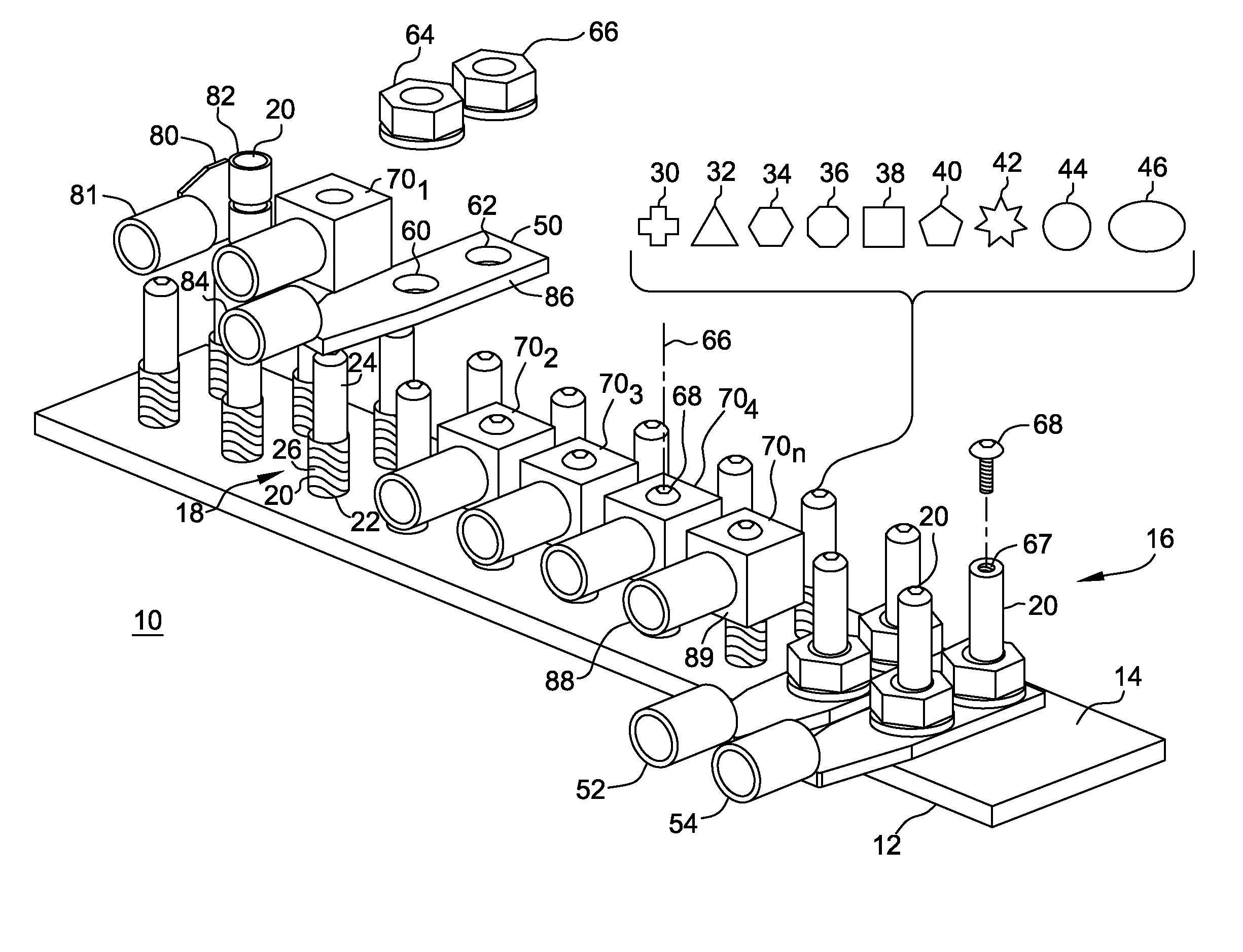
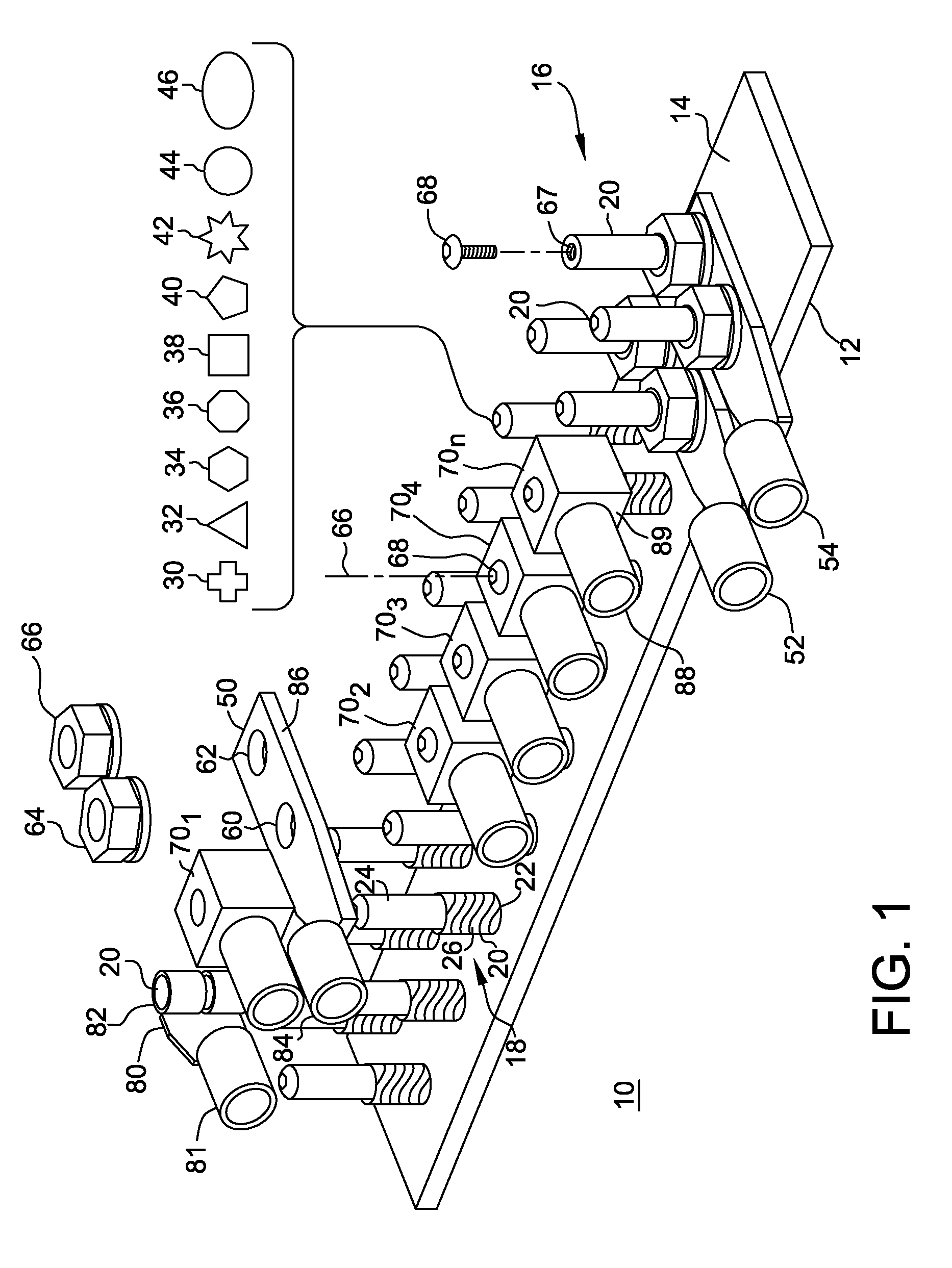
[0025]FIG. 1 is a perspective illustration of an embodiment of an electrical termination structure according to the teaching of the present application employed with first representative terminating structures. In FIG. 1, an apparatus 10 includes a base member 12 presenting a face 14 upward in FIG. 1. A plurality of electrically conductive connection members 16 are in electrical and physical connection with base member 12 extending from face 14 upward in FIG. 1.

[0026]In the interest of avoiding prolixity and cluttering of FIG. 1, it may be considered that each respective connection member of plurality of connection members 16 is substantially the same, except as described below in connection with rod shape. Accordingly, a representative connection member 18 will be described in detail with the understanding that remaining connection members of plurality of connection members 16 are substantially similar to representative connection member 18. Connection member 18 presents a rod-shap...


PUM


Abstract

An apparatus for effecting electrical termination with a plurality of types of termination structures includes: (a) a base member presenting a face in a first direction; and (b) a plurality of electrically conductive connection members extending in the first direction from the face. Each respective connection member of the plurality of connection members presents a rod-shaped post. Each post has a first portion presenting a threaded structure and has a second portion presenting an unthreaded structure. The rod-shaped post of selected connection members may further include a tapped opening located along a longitudinal axis of the respective connection member.

Description

[0001]This application claims benefit of prior filed Provisional Patent Application Ser. No. 61 / 309,546, filed Mar. 2, 2010.BACKGROUND OF THE INVENTION[0002]The present invention is directed to electrical termination structures and methods, and especially to electrical termination structures and methods accommodating a plurality of different termination structures.[0003]In the past high power electrical termination structures have been designed to accept one type of connector such as bolted lugs or a quick-connect terminals. A user of such electrical termination structures must choose a connection technology when ordering an end product. Such a requirement for early selection of connection technology can result in a user having to maintain inventory of more than one connection technology, and could result in having to scrap connectors if a user decides to change connector technology. An installer making a connection in the field connection may have to cut off a connector from a cabl...

Claims


Application Information

Patent Timeline
Patent Type & Authority Patents(United States)
IPC IPC(8): H01R11/11
CPCH01R4/30H01R4/305H01R9/2475H01R13/642
Inventor STEEVES, MICHAEL, C.
Owner ACLEAP POWER INC
Learn More