
Fixing device for a tool member

a fixing device and tool member technology, applied in the field of fixing devices, can solve the problems of oxidizing the threaded structure of the threaded hole or the threaded screw, the fixing device still has a disadvantage, and the fixing device is going to be damaged someday

Active Publication Date: 2014-02-18
CHEN SHOU HUNG
View PDF1 Cites 4 Cited by
  • Summary
  • Abstract
  • Description
  • Claims
  • Application Information

AI Technical Summary

Benefits of technology

The present invention is an improved fixing device for a tool member and a connector. The device includes a handle with a receiving space for the connector, a tool member with an operation head, a connecting end for connecting to the connector, and a fixing unit for securing the tool member to the connector. The connector has an engaging rib and an engaging unit in the handle securely fixes the tool member to the connector. A detaching member is assembled into the handle for safely detaching the engaging rib from the engaging unit. The detaching member has an abutting space for smoothly detaching the connector from the receiving space. A cover is assembled at the other end of the handle with a receiving room communicating with the receiving space of the handle. The technical effect of the invention is to provide a more convenient and efficient fixing device for a tool member and a connector.

Problems solved by technology

However, when a tool member (such as a scraper body or a saw body) of the tool assembly is broken, a user has to exchange the tool member.
However, the conventional fixing device still has a disadvantage as following:
When the moisture in the air is absorbed by the threaded hole or the threaded screw, the threaded structure of the threaded hole or the threaded screw often oxidizes and is going to be damaged someday.
Therefore, the user has to replace the whole tool assembly rather than replace the only tool member, when the tool member is damaged.

Method used


Image

  • Fixing device for a tool member
  • Fixing device for a tool member
  • Fixing device for a tool member

Examples


Embodiment Construction

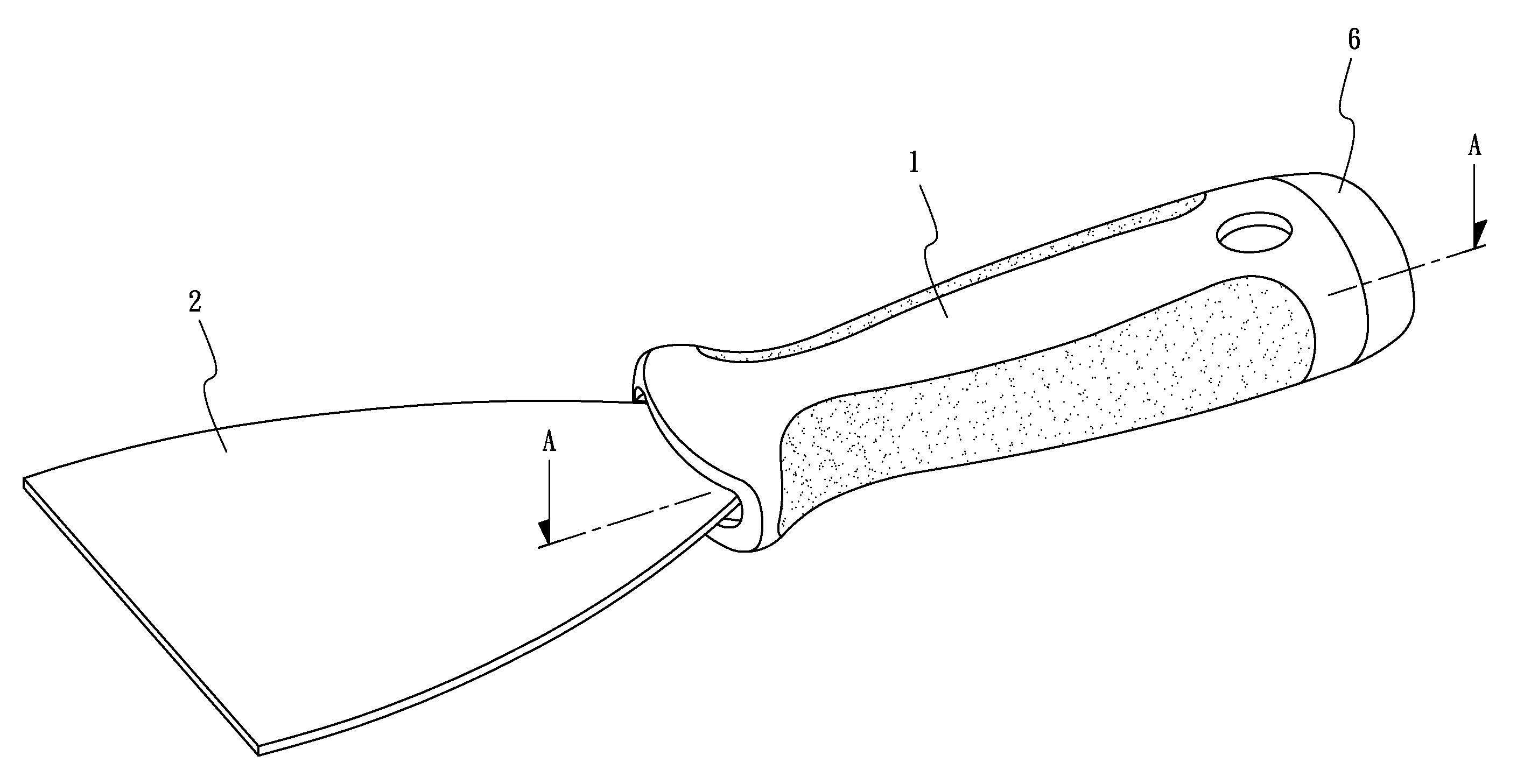
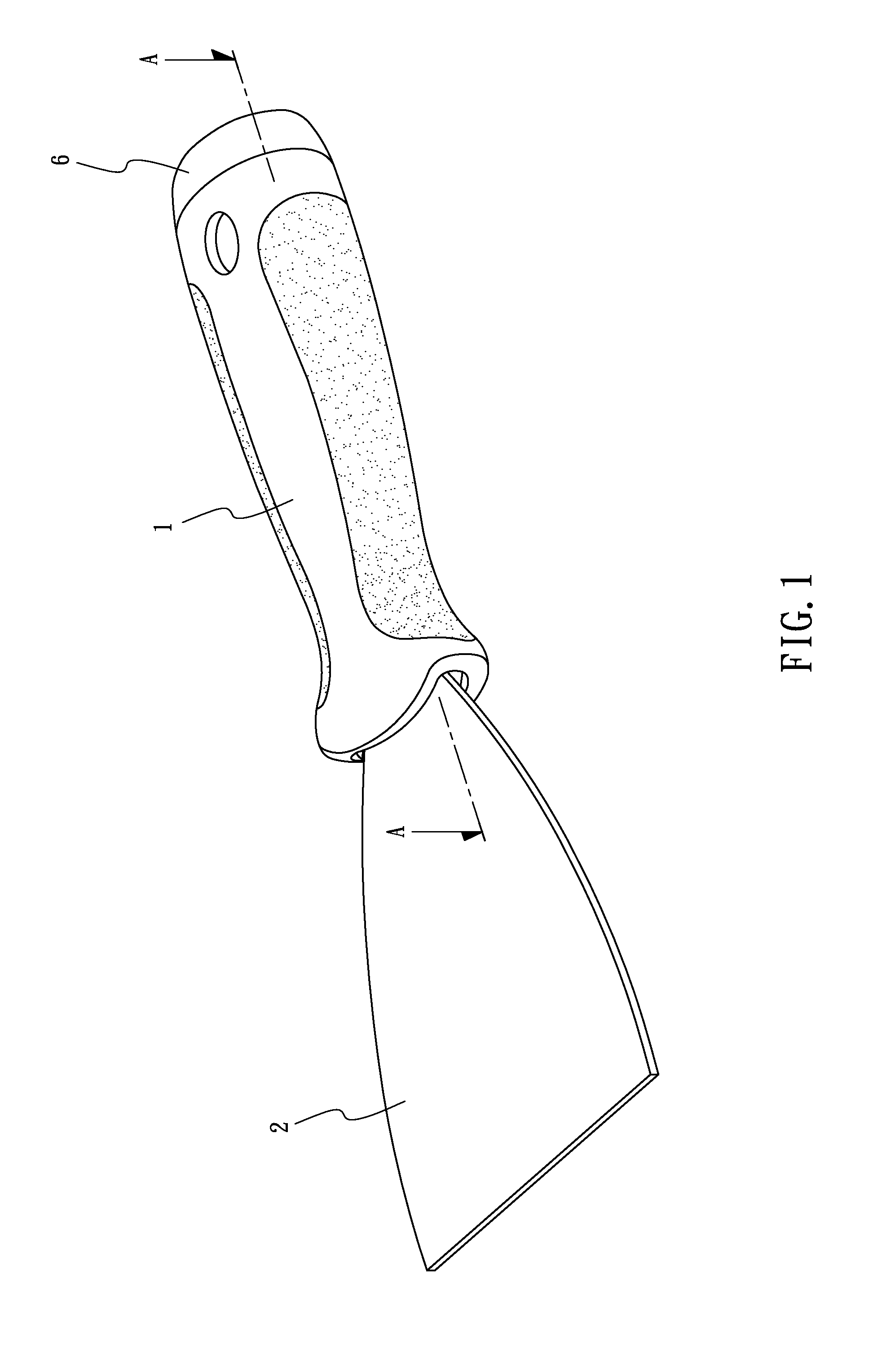
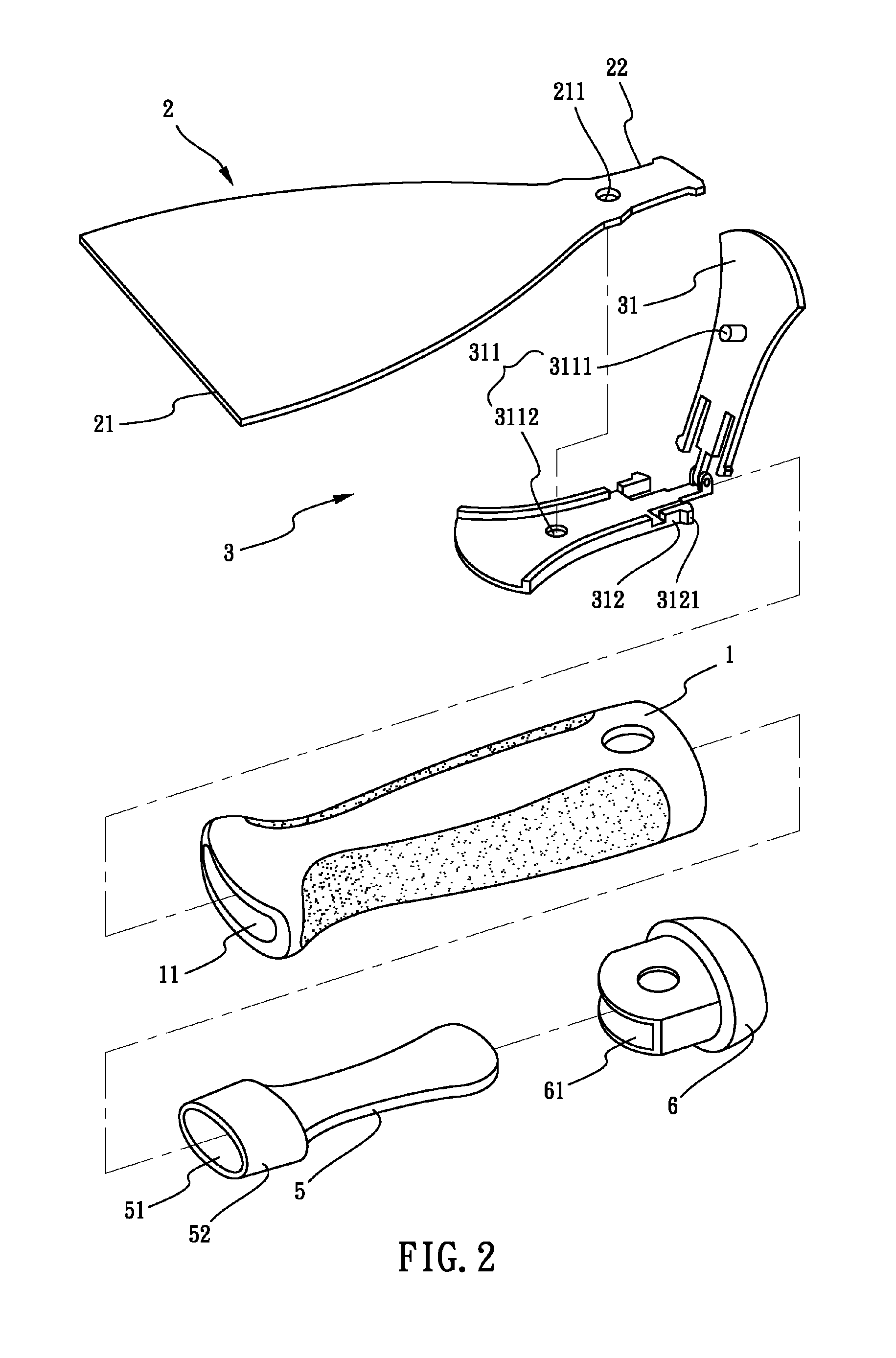
[0020]Referring to FIGS. 1-4, a fixing device for a tool member 2 in accordance with the present invention comprises a handle 1, the tool member 2 and a connector 3. The handle 1 has a receiving space 11 defined therethrough. The receiving space 11 is used to receive the connector 3 when the connector 3 is inserted into the receiving space 11. The connector 3 is received in one end of the receiving space 11 of the handle 1. The tool member 2 has an operation head 21 defined at one end thereof. The operation head 21 is provided for a user to operate. A connecting portion 22 is defined at the other end of the tool member 2. The connecting portion 22 is connected to the connector 3. The connector 3 has two flat bodies 31. The two flat bodies 31 are pivoted with each other so that the connector 3 can be opened or closed so as to clamp the connecting portion 22 of the tool member 2. The connector 3 has a fixing unit 311 to fix the connecting portion 22 of the tool member 2. The connector...


PUM


Abstract

A fixing device for a tool member includes a handle having a receiving space opened at one end thereof for receiving a connector, the tool member having an operation head defined at one end thereof, a connecting end defined at another end of the tool member for connecting to the connector, the connector having two flat bodies which are pivoted with each other, a fixing unit defined between the two flat bodies for fixing the connecting end of the tool member to the connector, the connector having at least one engaging rib defined at one end thereof for engaging with a wall of the receiving space. Therefore, the tool member is easily detachable from the handle via the connector.

Description

CROSS-REFERENCE TO RELATED APPLICATION[0001]This application is a Continuation-in-part Application of Ser. No. 13 / 442,797 filed 9 Apr. 2012, and entitled “FIXING DEVICE FOR A TOOL MEMBER”, now pending.BACKGROUND OF THE INVENTION[0002]1. Field of the Invention[0003]The present invention relates to a fixing device and more particularly to a fixing device for a tool member.[0004]2. Description of Related Art[0005]A tool assembly, such as a scraper assembly or a saw assembly, is often used for gardening. However, when a tool member (such as a scraper body or a saw body) of the tool assembly is broken, a user has to exchange the tool member. Therefore, a conventional fixing device for a tool member comes to the world.[0006]The conventional fixing device for a tool member comprises a handle body. The handle body further has a connecting slot. At least one through hole is opened on the handle body. The through hole communicates with the connecting slot. A tool member has a connecting end w...

Claims


Application Information

Patent Timeline
Patent Type & Authority Patents(United States)
IPC IPC(8): B25H3/00B25G3/00B25B3/00B25G1/00B25B27/00
CPCB25G3/24B25G3/18
Inventor CHEN, SHOU-HUNG
Owner CHEN SHOU HUNG
Learn More