Method for controlling vacuum pumps in an industrial furnace complex

a technology of industrial furnaces and vacuum pumps, applied in the direction of furnaces, muffle furnaces, instruments, etc., can solve the problems of not being able to engage or disable the vacuum pumps throughout the entire process, not being able to exercise corresponding control/regulation of the vacuum pump, and being unable to measur

Inactive Publication Date: 2014-04-08
IPSEN INT
View PDF3 Cites 2 Cited by
  • Summary
  • Abstract
  • Description
  • Claims
  • Application Information

AI Technical Summary

Benefits of technology

[0036]The object of the invention is to provide an intelligent method for controlling vacuum pumps used in an industrial furnace complex, particularly in vacuum furnace systems, in which the incremental deactivation or activation of the pumps throughout the entire process exerts an influence on a corresponding controller / regulator for the vacuum pump in such manner that the vacuum pumps are switched off as a function of the pressure-time sequences in the process phases in which a vacuum is not present, thus enabling the overall workflow of the treatment process to be operated as economically as possible in terms of energy consumption.
[0045]The incremental deactivation or activation of the vacuum pump using the program in the process controller with the four logically linked program steps makes it possible to control the vacuum pumps economically in terms of energy and without extensive investment according to the features of the claims.

Problems solved by technology

With this method for controlling the process gas, it is only possible to measure the current state of the furnace atmosphere regularly during the carburising phase.
However, with this method it is not possible to engage or disable the vacuum pumps throughout the entire process according to the status of the process concerned.
However, it does not exercise any corresponding control / regulation of the vacuum pump.
Accordingly, the general process sequence represented in both patents also does not disclose how the vacuum pump might be controlled or regulated.
While this regulation of the suction power of a pump is economical in terms of energy consumption, it is not able to isolate the pumps from the recipient by means of a valve if overpressure phases occur in the vacuum furnace during high pressure gas quenching or convection operation for example.
The disadvantage of such economical regulation of a pump's suction power by varying its suction or speed is also that the system cannot determine when the pumps are isolated from the recipient by a valve.
With this method and device for pressure regulation in vacuum systems, it is possible to regulate the suction power, but the “intelligence” of the system is limited by the fact that a switch-off function is not triggered in the process phases that are performed without a vacuum.
In view of the above, it may be concluded that the problem of obtaining information about when the vacuum pumps can be shut off entirely after a certain point in time while process gas is being evacuated at certain times in a given process has not yet been solved.

Method used


Image

  • Method for controlling vacuum pumps in an industrial furnace complex
  • Method for controlling vacuum pumps in an industrial furnace complex
  • Method for controlling vacuum pumps in an industrial furnace complex

Examples


Embodiment Construction

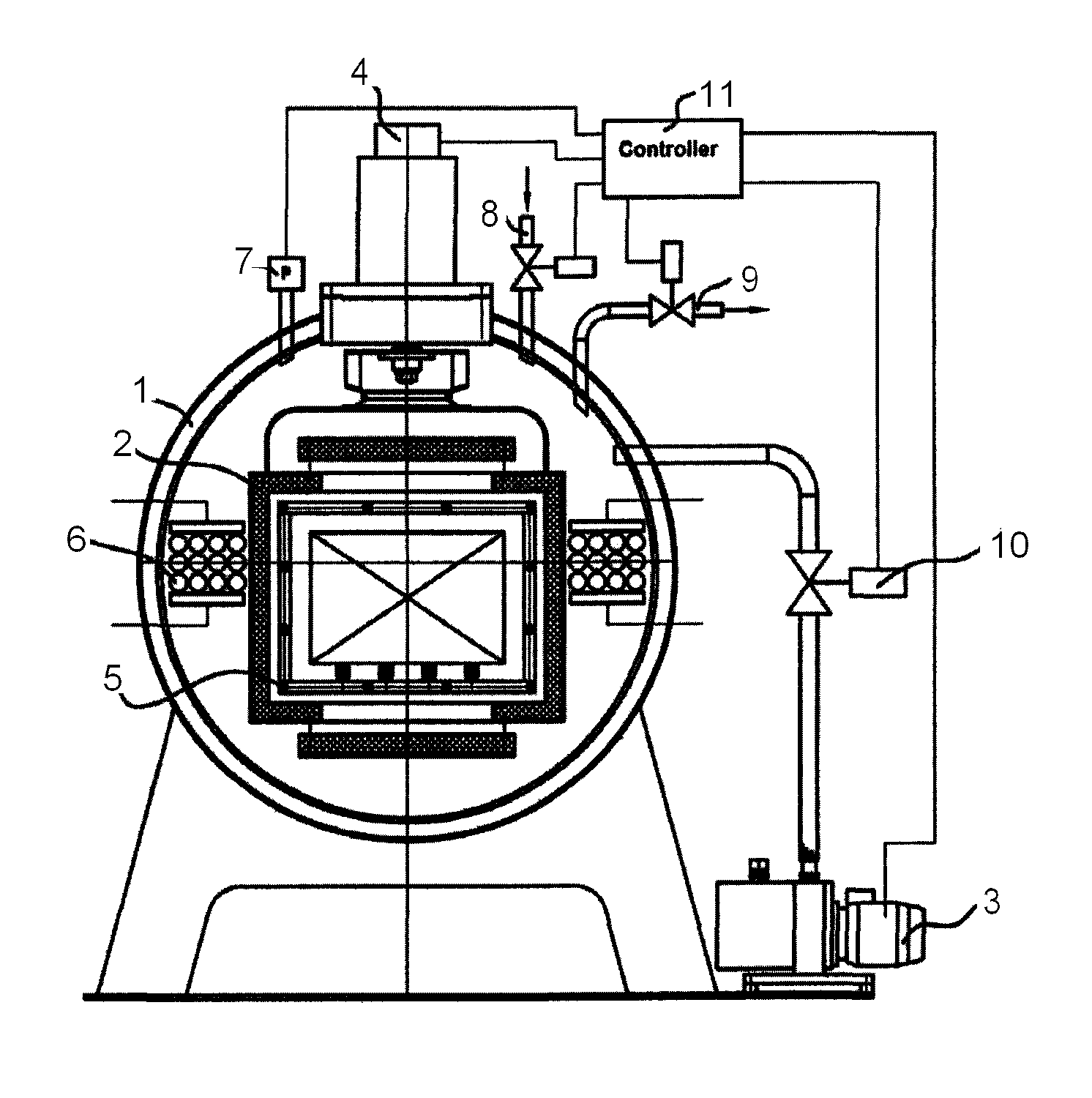
[0061]In an industrial furnace complex 1, shown in FIG. 2, operated as a vacuum furnace system and comprising a heating chamber 2 and a vacuum pump 3 with heating unit 6, a pressure sensor 7, a gas inlet 8 and pump valve 10 are connected to a vacuum pump controller 11 having a logic circuit. A motor-fan unit 4 ensures that a coolant gas is circulated from a coolant gas reservoir 5, though this subprocess does not need to be described in greater detail here.

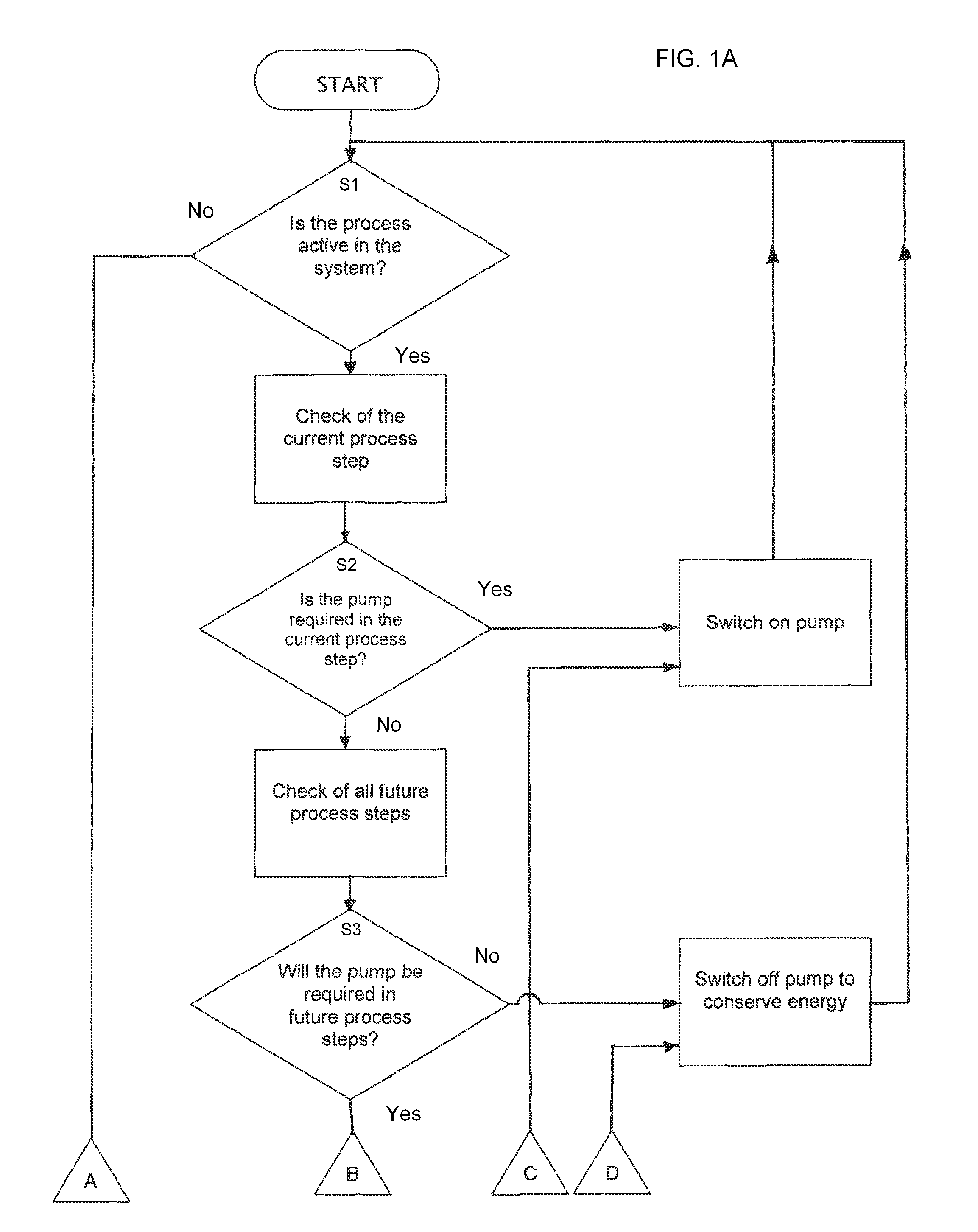
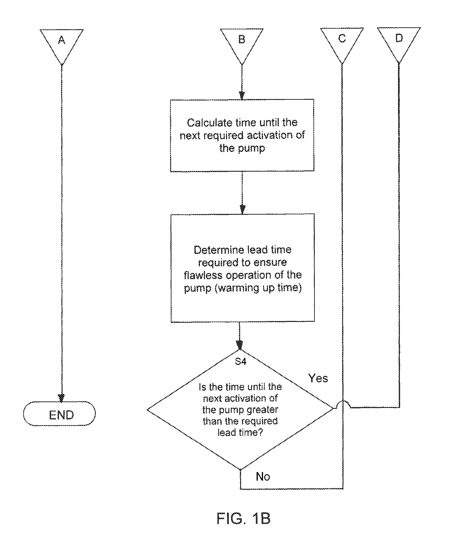
[0062]According to the method, a method for switching vacuum pump 3 off or on in steps depending on whether a vacuum is needed or not is carried out on the basis of pressure-time sequences in order to control vacuum pump 3. As shown in FIGS. 1A and 1B, to this end a program is used including the program steps of[0063]a query S1, as to whether a heat treatment process is active in industrial furnace complex 1,[0064]a query S2, as to whether vacuum pump 3 is required in a current phase of the heat treatment process,[0065]a query S3,...


PUM

PropertyMeasurementUnit
time T1aaaaaaaaaa
time T2aaaaaaaaaa
lead time T2aaaaaaaaaa

Abstract

Energy-efficient control of a vacuum pump having a pump controller integrated in a control and regulation device used in an industrial furnace complex is disclosed. A method and an industrial furnace complex provide incremental deactivation or activation of the vacuum pump depending on whether a vacuum is needed by using a program having one or more program steps, including a first query about whether a heat treatment process is active in the industrial furnace, a second query about whether the vacuum pump is required in a current phase of the heat treatment process, a third query about whether the vacuum pump will be required in a future phase of the heat treatment process, and / or a fourth query about whether a time until the next operation is greater than a required lead time for the vacuum pump to warm up.

Description

BACKGROUND OF THE INVENTION[0001]1. Field of the Invention[0002]The invention relates to an intelligent control method for vacuum pumps used in an industrial furnace complex, particularly in vacuum furnace systems. The invention also relates to an industrial furnace complex associated therewith.[0003]2. Description of the Related Art[0004]According to DE 10152204 B4, the stated object is to improve a vacuum gas carburising complex so as to avoid the drawbacks of not being able to monitor and record data relating to a carburising atmosphere during the carburising process.[0005]In this context, the following steps are carried out in a method for measuring and / or regulating the carburising atmosphere inside a carburising chamber of a vacuum gas carburising system:[0006]1.: Introducing workpieces into the carburising chamber;[0007]2.: Creating and maintaining a vacuum in the carburising chamber;[0008]3.: Introducing a carburising gas into the carburising chamber;[0009]4.: Measuring the ...

Claims


Application Information

Patent Timeline
Patent Type & Authority Patents(United States)
IPC IPC(8): G05D7/00
CPCF27B5/16C21D1/74C21D1/773C21D11/00F27B5/18
Inventor MUHLHAUS, THOMAS
Owner IPSEN INT
Why Eureka
Try Eureka