Trigger grip

a trigger grip and trigger technology, applied in the field of trigger grips, can solve the problems of inconvenient use and many drawbacks of prior art wire grips

Inactive Publication Date: 2014-05-13
LIU JAMES KE +1
View PDF17 Cites 20 Cited by
  • Summary
  • Abstract
  • Description
  • Claims
  • Application Information

AI Technical Summary

Problems solved by technology

However, the prior art wire grip suffers a number of drawbacks.
Further, a user has to use both hands to pull the projection to open the jaws prior to wire installation.
This is very inconvenient in use.

Method used


Image

  • Trigger grip
  • Trigger grip
  • Trigger grip

Examples


Embodiment Construction

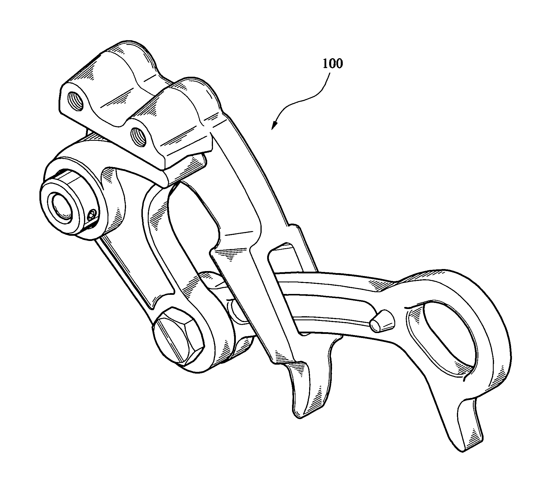
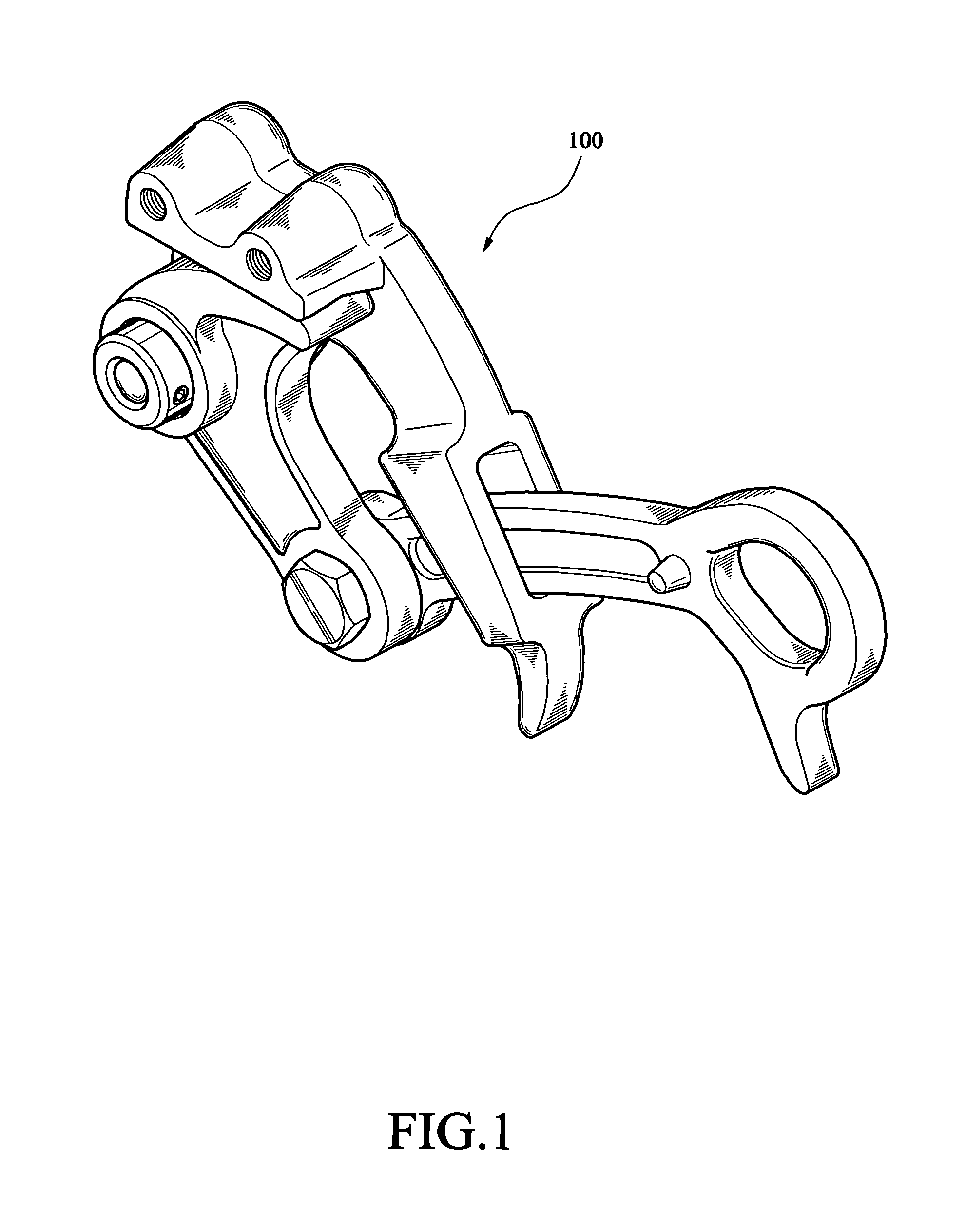
[0021]Referring to FIGS. 1 to 9, a trigger grip 100 in accordance with a first preferred embodiment of the invention comprises a body 10, a pivotal link 20, a lever 30, and a pivotal plate 40 each discussed in detail below.

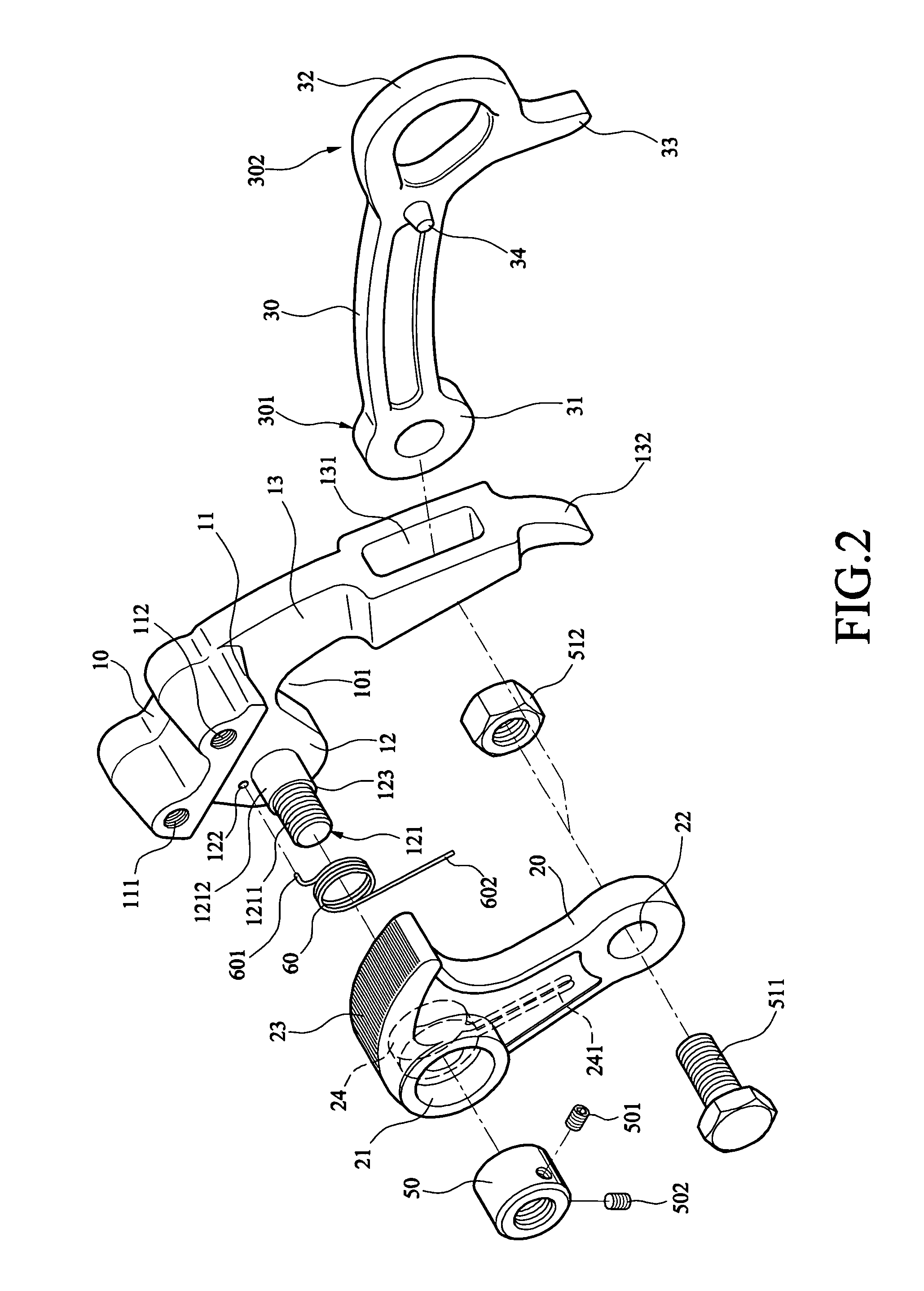
[0022]The body 10 comprises a curved bottom recess 101, an upper jaw 11 extending laterally, two spaced threaded holes 111, 112 on top of the upper jaw 11, a pivot section 12 provided on one side of the recess 101, and a sleeve section 13 provided on the other side of the recess 101.

[0023]The pivot section 12 comprises a solid, stepped-diameter, cylindrical projection 121 projecting laterally. A positioning hole 122 is provided on the pivot section 12 proximate an enlarged base 1212 of the projection 121. The projection 121 further comprises external threads 1211 and a shoulder 123 at a joining portion of the threads 1211 and the base 1212. The provision of the projection 121 can prevent the body 10 from being adversely deformed or even breaking.

[0024]The sleeve s...


PUM


Abstract

A trigger grip (100) includes a body (10) including an upper jaw (11) extending laterally, a pivot section (12) depending from one end of the upper jaw, and a sleeve section (13) depending from the other end of the upper jaw, the sleeve section including a slot (131) and an extension (132) depending from the slot; a pivotal link (20) pivotably secured to the pivot section (12) and including a jaw member disposed below the upper jaw (11) in an inoperative position; and a lever (30) including a first hole (31) at one end, a second hole (32) at the other end, and a protuberance (33) depending from the other end, the lever (30) being inserted through the slot (131) with its first hole (31) pivotably secured to the pivotal link (20).

Description

BACKGROUND OF THE INVENTION[0001]1. Field of the Invention[0002]The invention relates to wire gripping tools and more particularly to a trigger grip.[0003]2. Description of Related Art[0004]Taiwan Utility Model Publication No. 529,214 entitled wire grip discloses a grip for installing wires. The grip comprises a body, a wedge, and a biasing member.[0005]The body has a base, an installation member at one end of the base for installing insulators on a utility pole, and two opposing upper jaws at the other end of the base for covering the top of the wedge. Also, core of a wire may be inserted into either side of the upper jaws.[0006]The wedge is provided on a wedge conductor surface of the body and is adapted to move thereon. Core of a wire may be inserted into a gripping section of the installation member. Next, the wire core is gripped by the gripping section.[0007]The biasing member is a spring member for making the wedge as a spring biased member. The biasing member is secured by a...

Claims


Application Information

Patent Timeline
Patent Type & Authority Patents(United States)
IPC IPC(8): F16G11/04
CPCA62B1/14F16G11/04Y10T24/3949Y10T24/3956Y10T24/3936F16G11/101F16G11/106A62B35/0056A62B35/0081
Inventor CHEN, CHI-YUAN
Owner LIU JAMES KE
Why Eureka
Try Eureka