Door assembly for walk-in bathtub

a technology for bathtubs and doors, applied in the field of door and hinge systems, can solve the problems of physical disabilities, reduced strength, balance and range of motion that are typically affecting the operation of the tub and its ease of use, and achieve the effect of improving the safety and convenience of us

a technology for bathtubs and doors, applied in the field of door and hinge systems, can solve the problems of physical disabilities, reduced strength, balance and range of motion that are typically affecting the operation of the tub and its ease of use, and achieve the effect of improving the safety and convenience of us

US8732871B2Active Publication Date: 2014-05-27SAFETY TUBS

Image

  • Door assembly for walk-in bathtub
  • Door assembly for walk-in bathtub
  • Door assembly for walk-in bathtub

Examples


Embodiment Construction

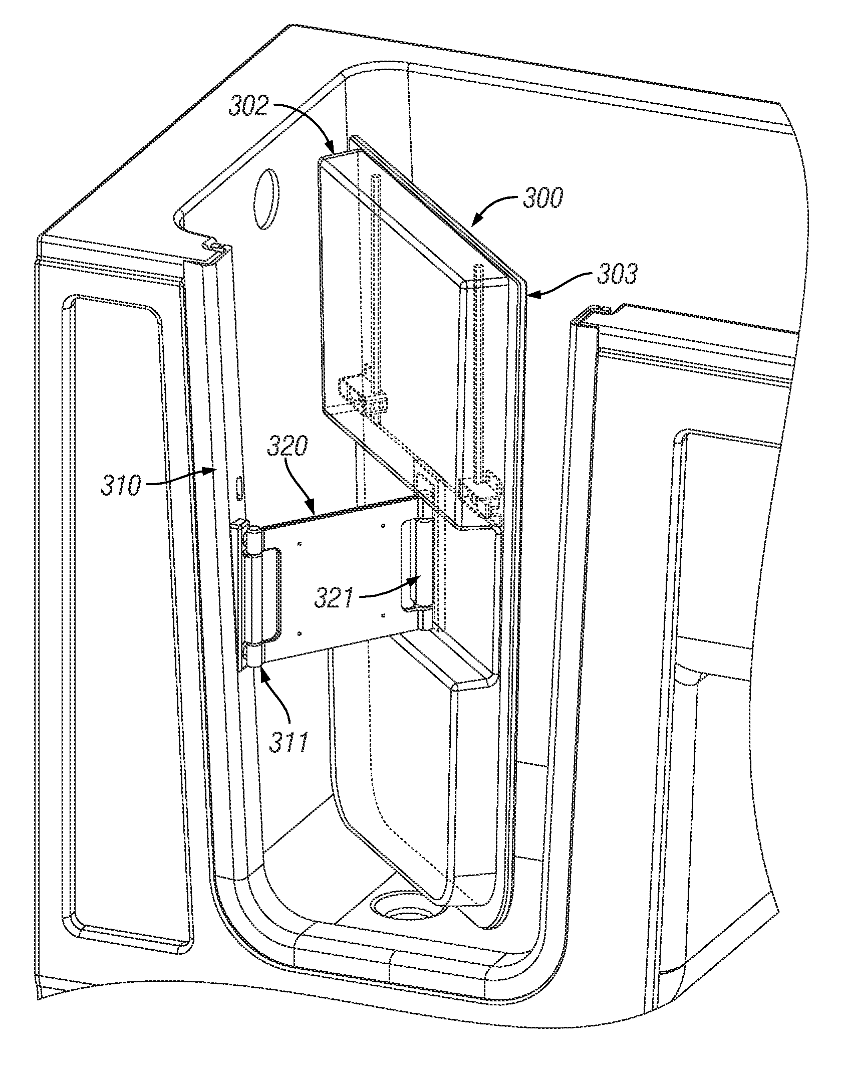
[0021]FIGS. 3A-3C show a perspective view of a lever hinged side door for a walk-in bath tub in accordance with a preferred embodiment of the present invention. FIGS. 3A-3C illustrate the manner in which the side door opens. Similarly, FIGS. 4A-4C show a top plan view of the lever hinged side door.

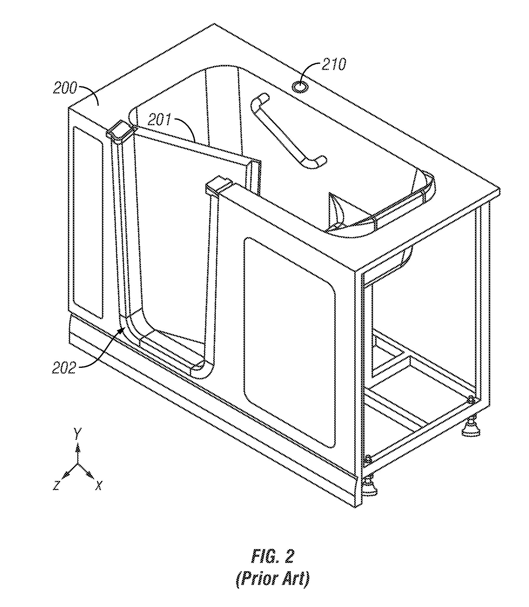
[0022]In the example shown, the lever hinged door 300 is mounted to a door frame 310 similar to the one shown in FIG. 2. However, it should be mentioned that the present invention can also be used with walk-in tubs that do not utilize a door frame around the threshold.

[0023]Unlike prior art designs, the door 300 in the present invention does not hinge directly on the door threshold. Instead, the door 300 is connected to the frame 310 by an intermediate double axis hinge 320. It is this double axis hinge 320 that is connected to the door frame 310 via a first hinge axis mount 311. The other end of the hinge 320 connects to approximately the middle of the door 300 by means of a second hinge ...


PUM


Abstract

The disclosure concerns a door assembly for a walk-in bathtub that includes a door that fits within a door threshold in the wall of the walk-in tub. The door assembly further comprises a hinge assembly that includes a first axis mount coupled to the door threshold and a second axis mount coupled to the outer side of the door. A double axis hinge is coupled to both axis mounts, to thereby connect the door to the bathtub. The double axis hinge is able to open the door towards the inside of the tub by pivoting about the first axis toward the inside of the bathtub as the door in turn counter rotates about the second axis at the distal end of the hinge, in the direction opposite to that of the hinge.

Description

CROSS-REFERENCE TO RELATED APPLICATIONS[0001]This application claims the benefit of and priority to U.S. Provisional Patent Application No. 61 / 169,621 filed Apr. 15, 2009, the technical disclosures of which are hereby incorporated herein by reference.TECHNICAL FIELD[0002]The present invention relates generally to walk-in bathtubs and more specifically to an improved door and hinge system for the side of the tub to allow easier access.BACKGROUND OF THE INVENTION[0003]Walk-in bathtubs comprise high tub walls with a high built in seat and a side door, allowing the user to walk into the tub from the side and sit down without having to climb down into a low bath tub. FIG. 1 shows a typical example of a walk-in bathtub in accordance with the prior art. Walk-in tubs are particularly suited for individuals who have physical limitations that make it difficult or dangerous to climb into and out of a regular, low bathtub or to stand up in a shower for extended periods of time. Such limitations...

Claims


Application Information

Patent Timeline
27 May 2014
Publication
US8732871B2
IPC
A47K3/02
CPC
E05D3/12; E05Y2900/114; E05D15/04; A47K3/006; E05D15/28
Inventors
NEIDICH, ANDRE J.; BUETE, ROBERT