Illuminating device, image reading apparatus including the illuinating device, and image forming apparatus including the image reading apparatus

a technology of illumination device and illumination device, which is applied in the direction of lighting and heating apparatus, printing equipment, instruments, etc., can solve the problems of reducing light loss and light loss, and achieve the effects of suppressing light loss, stably illuminated irradiated objects, and uneven illumination

Active Publication Date: 2014-06-17
SHARP KK
View PDF25 Cites 8 Cited by
  • Summary
  • Abstract
  • Description
  • Claims
  • Application Information

AI Technical Summary

Benefits of technology

[0031]According to the present invention, light-emitting elements and a reflective member are disposed such that the passing path of light reflected by an irradiated object runs therebetween, and a light-guiding member is provided on the light-emitting element side. The light-guiding member includes a direct emission unit that is disposed between the irradiated object and the light-emitting elements, and that transmits light from the light-emitting elements toward the irradiated object, and an indirect emission unit that is disposed between the reflective member and the light-emitting elements, and that transmits light from the light-emitting elements toward the irradiated object via the reflective member. A light incidence face of the direct emission unit and a light incidence face of the indirect emission unit are disposed at mutually different positions around the light-emitting elements, and the light-emitting elements are disposed on the side of an interior angle formed by the light incidence faces. Accordingly, light emitted from the light-emitting elements emits along either a direct path extending from the direct emission unit to the irradiated object, or an indirect path extending from the indirect emission unit to the irradiated object via the reflective member, thereby illuminating the irradiated object. Although since one of the paths, namely, the direct path, is short, light incident on the irradiated object is scarcely dispersed such that it is possible to illuminate the irradiated object clearly with the incident light reaching through the direct path, the irradiated object is readily illuminated unevenly. Also, although since the other path, namely, the indirect path, is long, light incident on the irradiated object is dispersed such that the level of illumination by the light reaching through the indirect path of the irradiated object is low, uneven illumination of the irradiated object rarely occurs. By combining illumination through the direct path with that through the indirect path, it is possible to stably illuminate the irradiated object while suppressing light loss.

Problems solved by technology

In this illuminating device, although it is desirable to cause all the light emitted from the light-emitting elements to enter the reading range of the document, actually, it is not possible to cause all the light to enter the reading range of the document, causing light loss, and thus reducing the light loss is desired.

Method used


Image

  • Illuminating device, image reading apparatus including the illuinating device, and image forming apparatus including the image reading apparatus
  • Illuminating device, image reading apparatus including the illuinating device, and image forming apparatus including the image reading apparatus
  • Illuminating device, image reading apparatus including the illuinating device, and image forming apparatus including the image reading apparatus

Examples


Embodiment Construction

[0040]Embodiments of the present invention will be described below in detail with reference to the attached drawings.

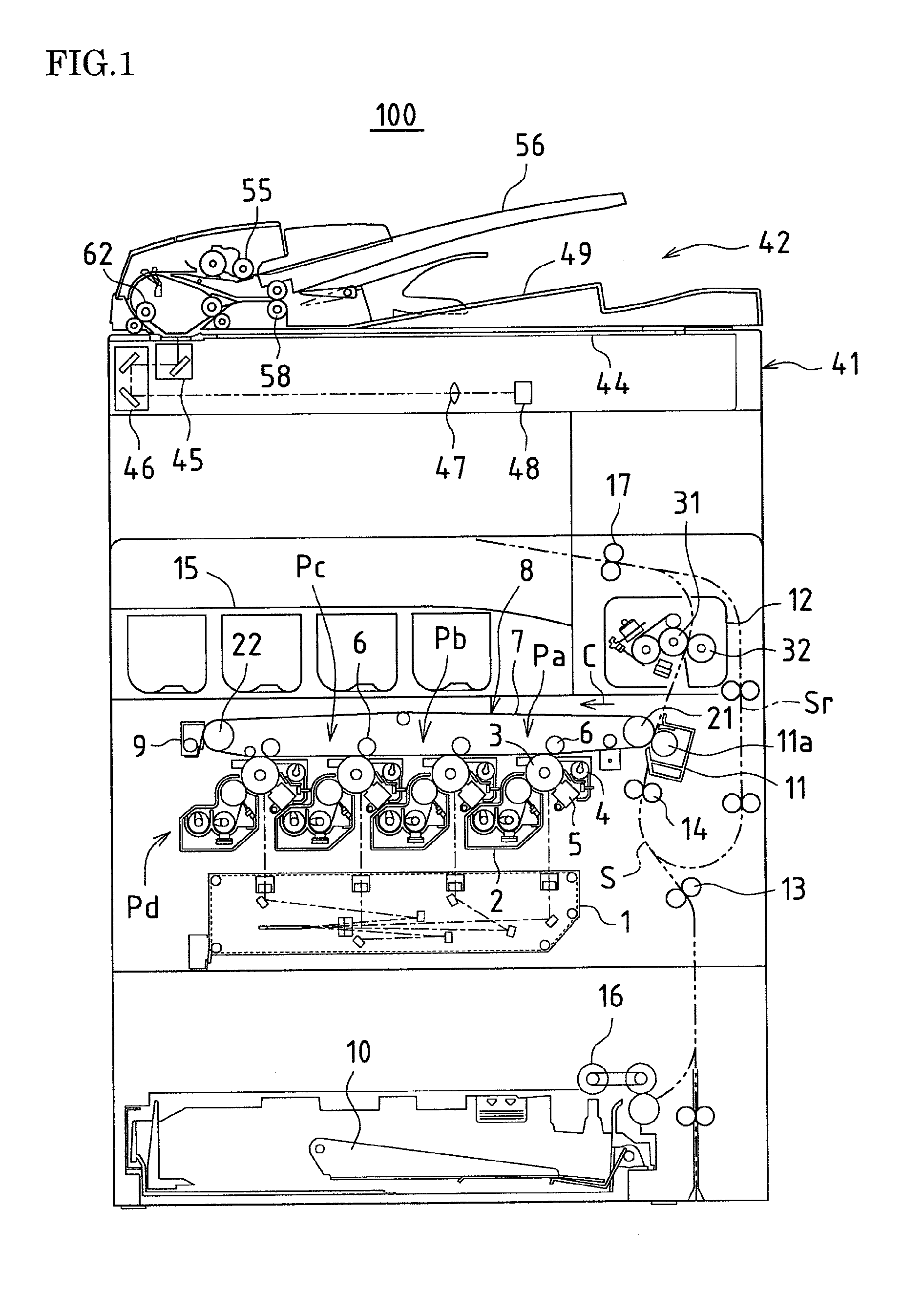
[0041]FIG. 1 is a cross-sectional view showing an image forming apparatus provided with an image reading apparatus to which an illuminating device according to an embodiment of the present invention is applied. The image forming apparatus 100 is a so-called multifunction peripheral having a scanner function, a copy function, a printer function, a facsimile function, and the like. The image forming apparatus 100 transmits an image of a document read by an image reading apparatus 41 to the outside (this function corresponds to a scanner function), and forms and records on a recording sheet, in color or monochrome, an image of the read document or an image received from the outside (this function corresponds to a copy function, a printer function, and a facsimile function).

[0042]The image forming apparatus 100 includes a laser exposure apparatus 1, development apparatuse...


PUM


Abstract

An illuminating device capable of stably illuminating an irradiated object such as a document while suppressing light loss with a simply structure is provided.An LED array (71) and a reflective plate (73) are disposed sandwiching a slit (St) through which light reflected by a document MS passes and a light-guiding member (72) is disposed on the side of the LED array (71). The light-guiding member (72) includes a direct emission unit (77) disposed between an illumination range y centered on a document reading position and the LED array (71) and an indirect emission unit (78) disposed between the reflective plate (73) and the LED array (71), a light incidence face of the direct emission unit (77) and a light incidence face of the indirect emission unit (78) are disposed at mutually different position around the LED array (71), and the LED array (71) is disposed on a side of an interior angle formed by the light incidence faces.

Description

TECHNICAL FIELD[0001]The present invention relates to an illuminating device that illuminates an irradiated object such as a document, an image reading apparatus including the illuminating device, and an image forming apparatus including the image reading apparatus.BACKGROUND ART[0002]Illuminating devices of this type are mounted on, for example, an image reading apparatus to be used, and each include a plurality of light-emitting elements (e.g., LEDs) that are arranged in a row and parallel to a main scanning direction for reading a document, and illuminate the document using these light-emitting elements. The image reading apparatus reads the entire document by repeatedly scanning the document being illuminated by the illuminating device along the main scanning direction, while scanning the document also in a sub-scanning direction. The image of the read document is output to a printer or the like to be recorded on a recording sheet.[0003]In this illuminating device, although it i...

Claims


Application Information

Patent Timeline
Patent Type & Authority Patents(United States)
IPC IPC(8): H04N1/04
CPCH04N2201/0094H04N1/193H04N1/00278H04N1/0285H04N1/02855H04N1/02865H04N1/02845H04N2201/0081H04N2201/02462G02B6/0031G03B27/542G02B6/0033G02B6/0055H04N2201/0434H04N1/1013G03G15/602G02B6/0045G02B6/0073G02B6/009G03G15/04
Inventor SUTO, YASUHIROYOSHIMOTO, MITSUHARUOKADA, TOMOHIKOYAMANAKA, HISASHIFUKUTOME, SHOHICHINAKANISHI, KENJI
Owner SHARP KK
Why Eureka
Try Eureka