
Injector element which maintains a constant mean spray angle and optimum pressure drop during throttling by varying the geometry of tangential inlets

a technology of injector elements and tangential inlets, which is applied in the direction of machines/engines, lighting and heating apparatus, instruments, etc., can solve the problems of difficult control of difficult control of the proper mixing and amount of fuel and oxidizer over the entire target throttling range, and inability to control the variable amount of fuel required for the desired thrus

Inactive Publication Date: 2014-07-01
NASA
View PDF19 Cites 18 Cited by
  • Summary
  • Abstract
  • Description
  • Claims
  • Application Information

AI Technical Summary

Benefits of technology

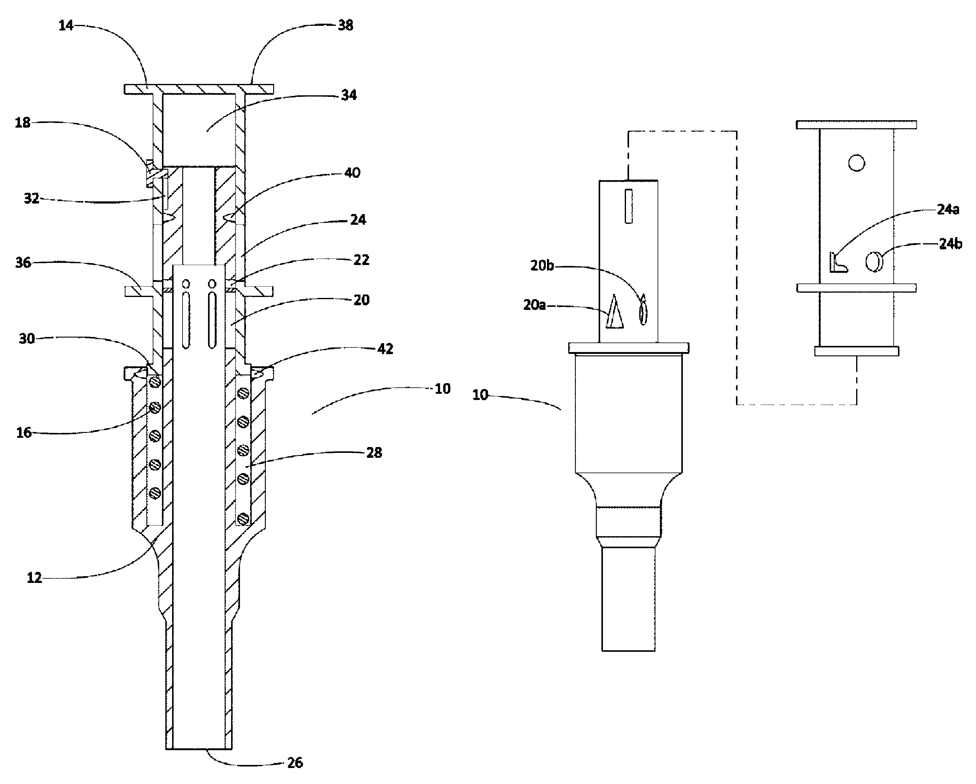
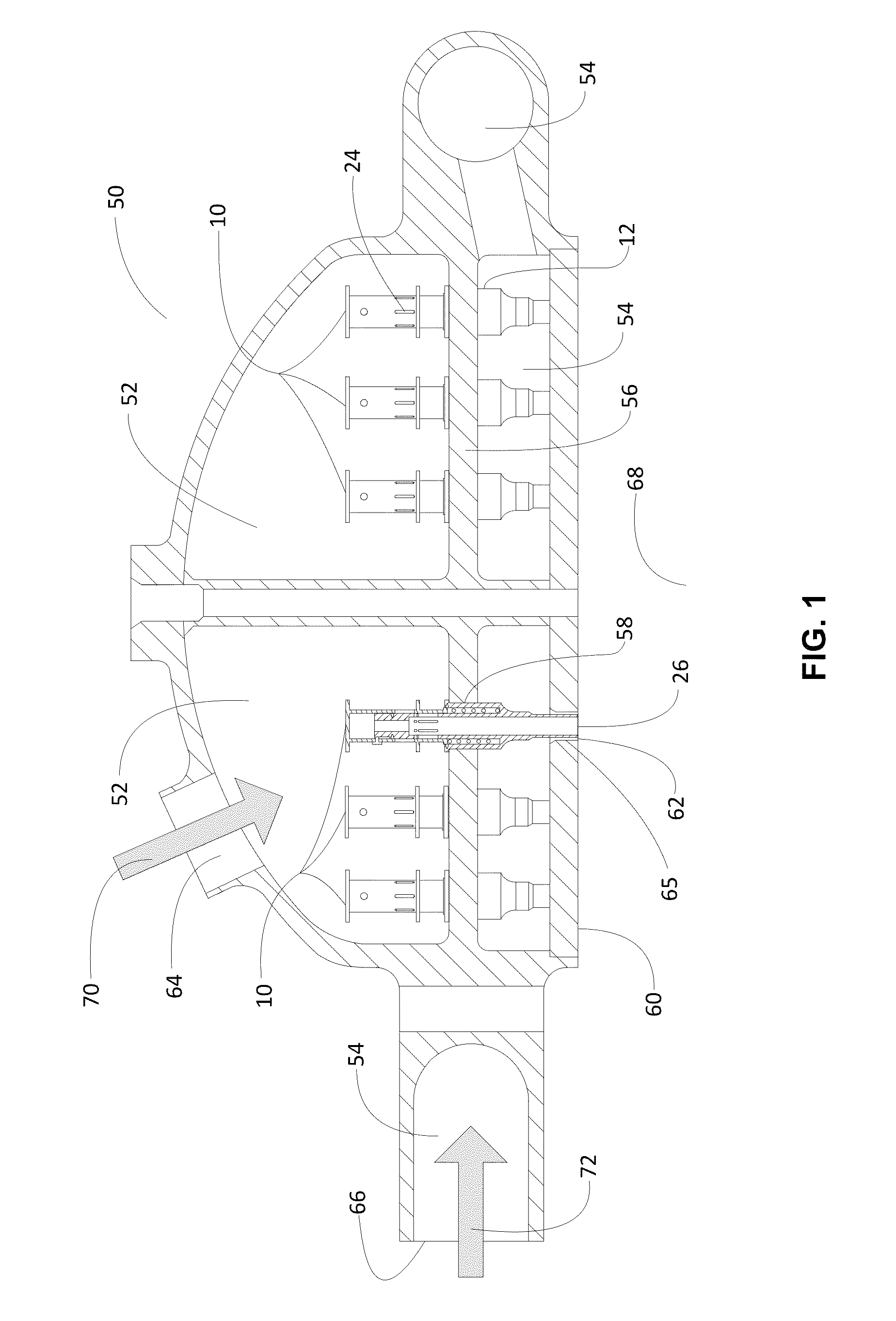
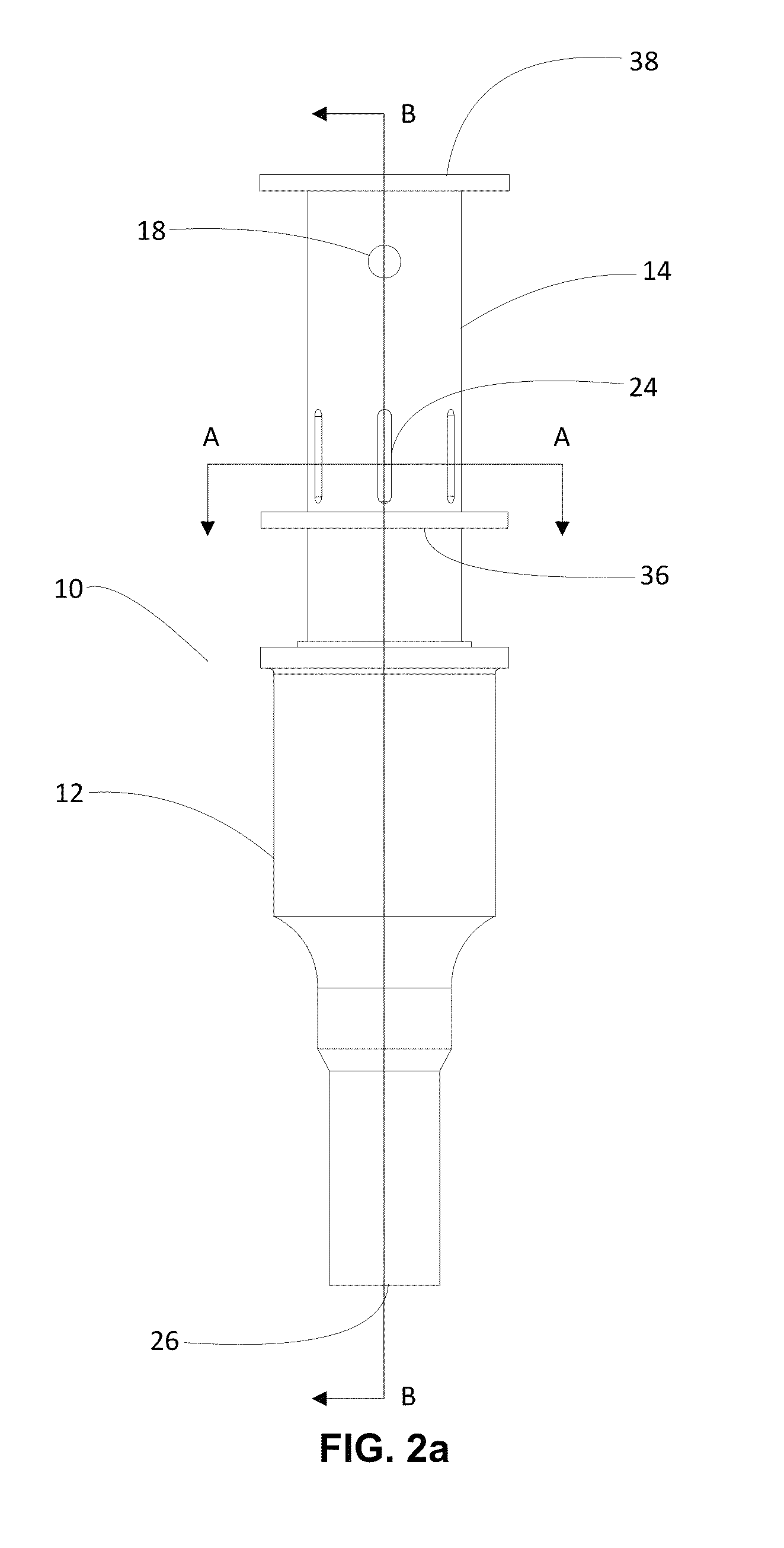
The present invention is a method for designing the optimum inlet geometry of a liquid rocket engine swirl injector. By calculating the tangential inlet area for each thrust level and determining the desired target spray angle and pressure value, a spring mechanism is designed to displace and align the tangential inlets with the injector tube, allowing flow to pass through. The resulting injector design has improved fuel efficiency and reduced emissions.

Problems solved by technology

Rockets having a variable thrust engine, therefore, can vary the propellant flow rate to meet the operational requirements while constant thrust engines cannot.
While variable thrust engines are desirable for some missions or solar system explorations, it is difficult to control the variable amount of fuel required for the desired thrust.
However, it is very difficult to control the proper mixing and amount of fuel and oxidizer over the entire target throttling range.
As a result, engines tend to chug at low power levels, which leads to engine and rocket damage.
In addition, the efficiency is also low at the lower power levels.
However, the variable inlet slot is only one physical means by which a mixing process can potentially be controlled.

Method used


Image

  • Injector element which maintains a constant mean spray angle and optimum pressure drop during throttling by varying the geometry of tangential inlets
  • Injector element which maintains a constant mean spray angle and optimum pressure drop during throttling by varying the geometry of tangential inlets
  • Injector element which maintains a constant mean spray angle and optimum pressure drop during throttling by varying the geometry of tangential inlets

Examples


Embodiment Construction

[0035]For the purpose of promoting an understanding of the present invention, references are made in the text to exemplary embodiments of an injector element, which maintains a constant mean spray angle and optimum pressure drop during throttling by varying the geometry of tangential inlets, only some of which are described herein. It should be understood that no limitations on the scope of the invention are intended by describing these exemplary embodiments. One of ordinary skill in the art will readily appreciate that alternate but functionally equivalent materials, components, and steps may be used. The inclusion of additional elements may be deemed readily apparent and obvious to one of ordinary skill in the art. Specific elements disclosed herein are not to be interpreted as limiting, but rather as a basis for the claims and as a representative basis for teaching one of ordinary skill in the art to employ the present invention.

[0036]It should be understood that the drawings are...


PUM

PropertyMeasurementUnit
constant mean spray angleaaaaaaaaaa
spray angleaaaaaaaaaa

Abstract

A method for determining the optimum inlet geometry of a liquid rocket engine swirl injector includes obtaining a throttleable level phase value, volume flow rate, chamber pressure, liquid propellant density, inlet injector pressure, desired target spray angle and desired target optimum delta pressure value between an inlet and a chamber for a plurality of engine stages. The tangential inlet area for each throttleable stage is calculated. The correlation between the tangential inlet areas and delta pressure values is used to calculate the spring displacement and variable inlet geometry. An injector designed using the method includes a plurality of geometrically calculated tangential inlets in an injection tube; an injection tube cap with a plurality of inlet slots slidably engages the injection tube. A pressure differential across the injector element causes the cap to slide along the injection tube and variably align the inlet slots with the tangential inlets.

Description

CROSS-REFERENCES TO RELATED APPLICATIONS[0001]This application is a continuation-in-part application of U.S. patent application Ser. No. 12 / 245,343, filed on Oct. 3, 2008 now abandoned and entitled “Liquid Propellant Injection Elements with Self-Adjusted Inlet Area for Rocket and Other Combustion-Type Engine Applications,” which is hereby incorporated by reference in its entirety.FEDERAL RESEARCH STATEMENT[0002]The invention described herein was made by employees of the United States Government and may be manufactured and used by or for the Government of the United States of America for governmental purposes without the payment of any royalties thereon or therefore.FIELD OF INVENTION[0003]This invention relates to propellant injection elements, and more specifically to an injector element, which maintains a constant mean spray angle and optimum pressure drop during throttling by varying the geometry of tangential inlets.TERMINOLOGY[0004]As used herein, the term “chamber pressure” re...

Claims


Application Information

Patent Timeline
Patent Type & Authority Patents(United States)
IPC IPC(8): F02K9/52F02K9/58
CPCF05D2250/51F23D11/26F02K9/58F05D2250/322F23D11/383F02K9/52G01L7/00G01B21/22G01F1/00G01N33/22G01L1/005F02K9/96
Inventor TRINH, HUU P.MYERS, WILLIAM NEILL
Owner NASA
Learn More