Foot snare device

a technology of snare device and foot, which is applied in the field of foot snare device, can solve the problems of steel traps not being set at the kill site, affecting the survival of causing the loss of hundreds of millions of dollars to livestock and agricultural industries, etc., and achieves the effects of reducing the risk of injury

Active Publication Date: 2014-08-05
UNIVERSAL SELECT A CATCH
View PDF47 Cites 0 Cited by
  • Summary
  • Abstract
  • Description
  • Claims
  • Application Information

AI Technical Summary

Benefits of technology

[0014]Links of kinkless chain are incorporated to go around the animal's lower leg; in tests this method has been shown to cause the least amount of foot damage, and when used in conjunction with a foot snare trigger mechanism, the snare lock capable of breaking away and opening the snare when larger non-target animals are captured, will also make the present invention an ideal animal capturing device.
[0015]One objective of the present invention is to provide a humane and selective foot snare that not only administers minimal injury to a captured animal, but also be as target specific as possible. In one embodiment of the present invention, the problem of leg damage is addressed by this device using a kinkless link chain to wrap around the captured animal's leg, causing little foot abrasion. The problem of developing a humane, selective and effective foot snare was further resolved in other embodiments by incorporating a snare cable with a short chain, breakaway S-hook, and a deer stop, with a one-way lock, and / or one of three anchoring device ends and a swiveled cable pulley equipped with snare attachment means, enabling the snare to work efficiently when used in conjunction with a snare triggering mechanism, such as the foot snare triggering mechanism device of Ser. No. 61 / 328,982, U.S. Patent and Trademark Office.
[0016]Another objective of the present invention is solving the problem of a limited loop size found in a throw arm type foot snare system, using an embodiment of the present invention with the addition of the swiveled cable pulley, enabling the use of a larger snare loop diameter, and greatly increasing the foot snare closing speed, when used in conjunction with a foot snare triggering mechanism device.
[0017]Another objective of the present invention is addressing foot abrasions by using a short piece of kinkless chain in one embodiment, or other non-abrasive material encircling the animal's leg, minimizing such abrasions and retaining foot blood circulation to reduce swelling.
[0018]Another objective of the present invention, addressing capture of non-target animals, is resolved in an embodiment by the use of an S-hook breakaway device, which is designed to open, releasing the animal when sufficient pressure is applied. The problem of capturing non-target smaller animals is minimized with the kinkless chain addition in an embodiment of the present invention, prevents the snare from closing completely, avoiding the capture of smaller legged animals. The problem of capturing smaller legged hoofed animals, such as deer or antelope in the medium diameter foot snare is resolved in one embodiment by using a deer stop, preventing the snare from closing completely, leaving enough room for a smaller legged animal to extract its leg.

Problems solved by technology

Every year hundreds of millions of dollars are lost to the livestock and agricultural industries due to animal predation and crop damage.
Also, if non-target animals such as domestic dogs are captured, they may be released generally unharmed.
Avoiding capture of larger animals, such as grizzlies, moose, elk and livestock, is a challenge when trapping for wolves.
In many cases steel traps cannot be set at a kill site due to bears being present, making it difficult to capture the predating animals.
Feral hogs are another species causing millions of dollars in domestic and agricultural damage every year.
Neck snares are somewhat effective, but when set under fence lines, the fence in many cases sustains damage once the hog is captured.
Several states have outlawed steel traps and control tools are limited.
None of the cited devices herein have the feature of a deer stop to prevent the capture of a deer-like animal.

Method used


Image

  • Foot snare device
  • Foot snare device
  • Foot snare device

Examples


Embodiment Construction

[0026]The present invention will now be described more fully hereinafter with references to the accompanying drawings, in which the preferred embodiment of the invention is shown. This invention may, however, be embodied in different forms, and should not be construed as limited to the embodiments set forth herein. Rather, the illustrative embodiments are provided so that this disclosure will be thorough and complete, and will fully convey the scope of the invention to those skilled in the art. It should be noted, and will be appreciated, that numerous variations may be made within the scope of this invention without departing from the principle of this invention and without sacrificing its chief advantages. Like numbers refer to like elements throughout.

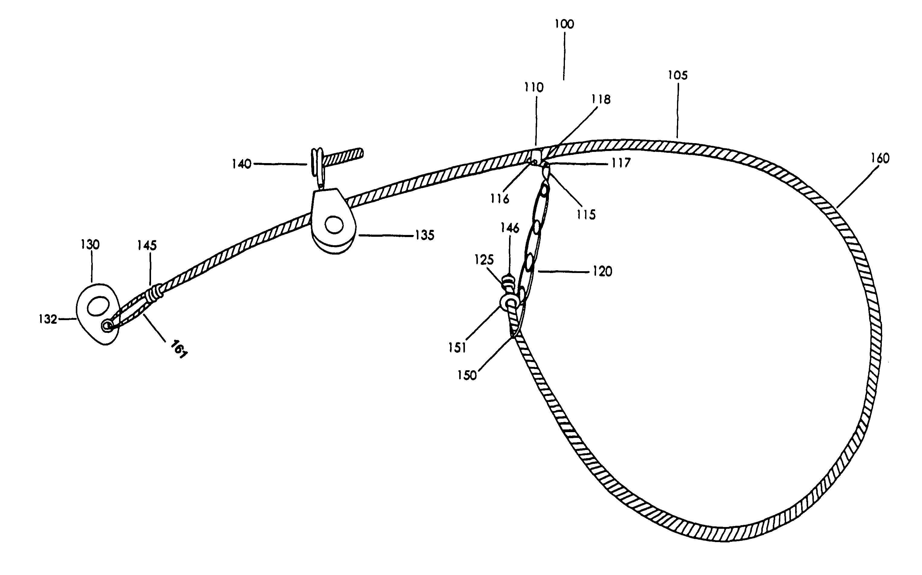
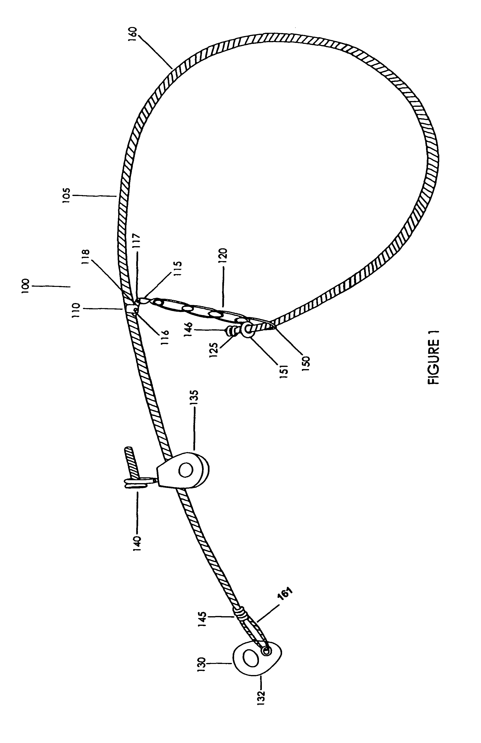
[0027]Turning now in detail to the drawings in accordance with the present invention, one embodiment of the present invention is depicted in FIG. 1, a foot snare device 100 comprising a snare cable 105 having an anchoring device end...


PUM


Abstract

The invention is an improved animal foot snare adapted to be used with a foot snare triggering device, comprising a snare cable with an anchoring device end and an opposite snare end and a chain with a loop slidably located on the snare cable proximal to the snare end. Said chain has a second locking end intermediately located along the cable, forming a noose with said cable. The locking end has a breakaway means in connection with a one-way locking means slidably attached to said cable which secures said chain to the snare cable for cinching the foot snare. Said device has a swiveled cable pulley slidably located along the snare cable between the locking end and the anchoring device end, where said pulley has a snare attachment means releasably installable to a foot snare triggering device, adapting the present invention to be used with foot snare triggering devices.

Description

FIELD OF THE INVENTION[0001]The present invention relates to a foot snare device, in particular to one used in combination with a foot snare triggering device, such as a spring triggered mechanism, for setting foot snare animal traps, modifying the conventional animal foot snare devices known in the industry.BACKGROUND OF THE INVENTION[0002]The capturing of animals for pelts and damage control is a long-practiced art. Through the years there have been attempts to make trapping devices more selective and humane. Several states and countries have now outlawed steel leg hold traps, and pressure continues to grow for more states to do the same. This humane selective foot snare device will be a valuable tool in capturing a wide variety of animals worldwide. Animal foot snare traps commonly operate via a triggering device to hold and then release a tensioned, trap-activating spring. This foot snare is a most humane, target specific leg-hold capturing device, easy to set with spring powere...

Claims


Application Information

Patent Timeline
Patent Type & Authority Patents(United States)
IPC IPC(8): A01M23/34
CPCA01M23/34
Inventor HOGGAN, MICHAEL, JAMES
Owner UNIVERSAL SELECT A CATCH
Why Eureka
Try Eureka