Rotary internal combustion engine

a technology of internal combustion engine and rotary piston, which is applied in the direction of combustion process, engine cooling apparatus, turbine/propulsion fuel heating, etc., can solve the problems of occupying less space and reducing the energy consumption of air compression, and achieves good heat exchange process, low energy consumption, and high efficiency.

Inactive Publication Date: 2006-10-24
STANEVICIUS ALGIMANTAS ALEKSANDRAS
View PDF4 Cites 2 Cited by
  • Summary
  • Abstract
  • Description
  • Claims
  • Application Information

AI Technical Summary

Benefits of technology

[0009]The main object of the present invention is to provide a rotary internal combustion engine with intermittent combustion cycle in the closed combustors that permits to keep higher gas temperature and higher pressure considerably increasing an engine efficiency. Another object of the invention is to provide a rotary internal combustion engine comprising a small compressor, capable to filter air efficiently and compress it by help of centrifugal forces, driving air into axial direction. Also—to provide a compressor capable to cool air from the beginning till the end of compression cycle, thereby considerably reducing consumption of energy for air compression. A further object of the invention is to provide a system converting the fuel to a gas that improves fuel mixing with air; thereby it improves the combustion process and reduces CO and NO in the exhaust. Another further object is to provide a stable engine with good brake action without using any additional devices. Summarizing the main purpose of the invention is to provide said engine with 1.5–2 times higher efficiency, which applicant believes to achieve, than all known engines and to eliminate aforementioned disadvantages.SUMMARY OF THE INVENTION
[0011]The efficient air compression is accomplished by the multi-stage compression rotor comprising the specially configured centrifugal-axial air driving impellers that rotate between stationary impellers inside of the compressor housing. This arrangement considerably decreases energy consumption for air compression and it takes less space than conventional centrifugal compressors.
[0014]An intermittent combustion cycle in the closed combustors and intermittent gas effect on the turbine blades permit 2–2.5 times to decrease amount of air supplied for combustion comparable with prototypes, and permit to rise gas temperature from 1000 degrees up to 1700 degrees C., that considerably improves efficiency of the engine.
[0015]The fuel heating by exhausted gas in the fuel heaters located in the exhaust ports, permits to convert fuel to a gas (in a moment of evaporating), when sprayed with highly compressed hot fuel to less compressed hot air at the combustors. An air mixes better with the gas than with small drops of fuel. This arrangement substantially improves combustion and reduces harmful amount of NO and CO in the exhaust.
[0018]According to the invention low energy consumption for air compression, good heat exchanging process by covering the combustors and the gas stream channels with the compressed air supply channels, heat saving by covering power housing and power body with thermal isolation, an intermittent combustion process in the closed combustors that permits considerably to rise gas temperature, and fuel converting to a gas allows to expect that the rotary combustion engine will be at least 1.5–2 times higher efficiency comparable with prototypes.

Problems solved by technology

This arrangement considerably decreases energy consumption for air compression and it takes less space than conventional centrifugal compressors.

Method used


Image

  • Rotary internal combustion engine
  • Rotary internal combustion engine
  • Rotary internal combustion engine

Examples


Embodiment Construction

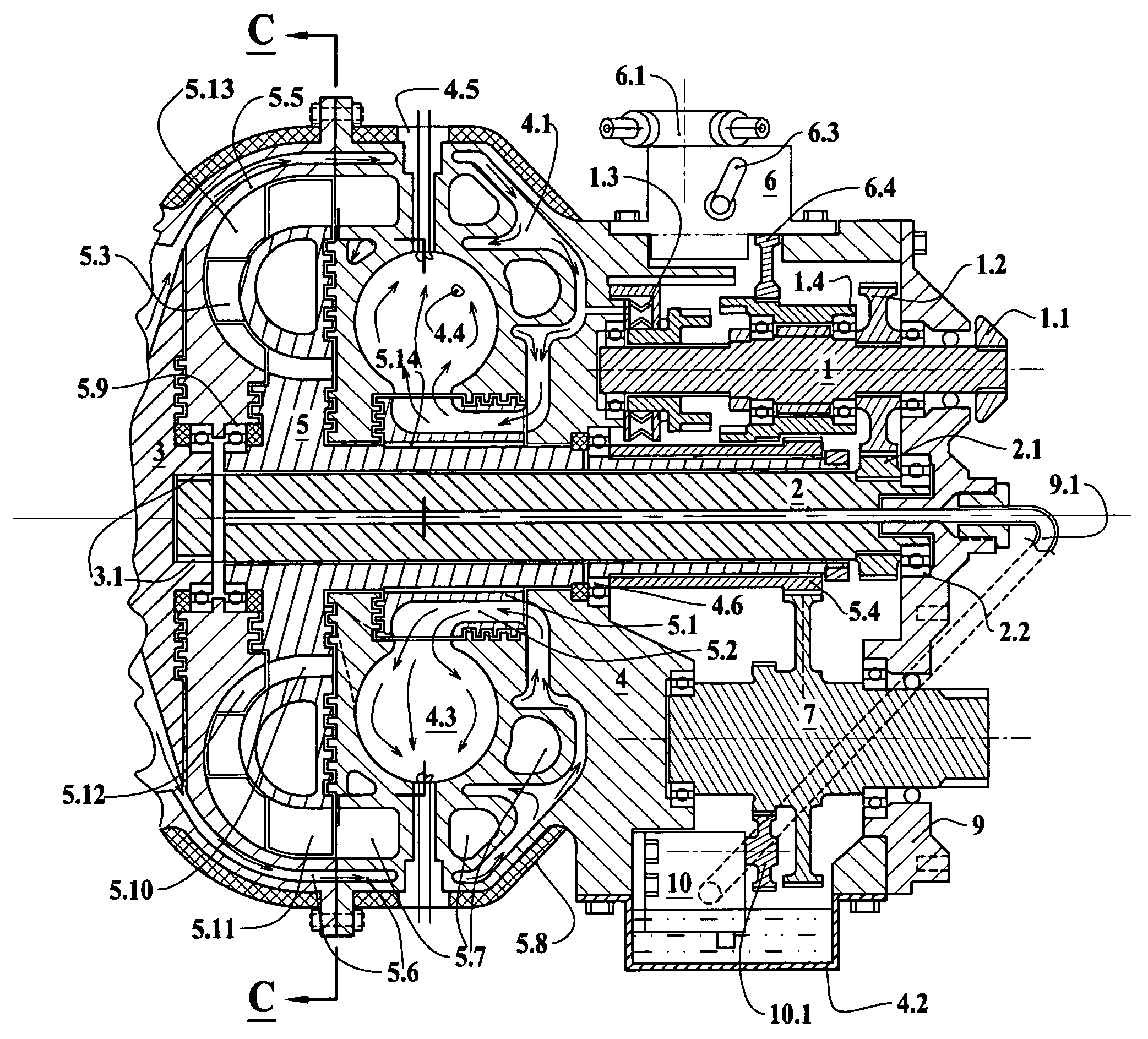
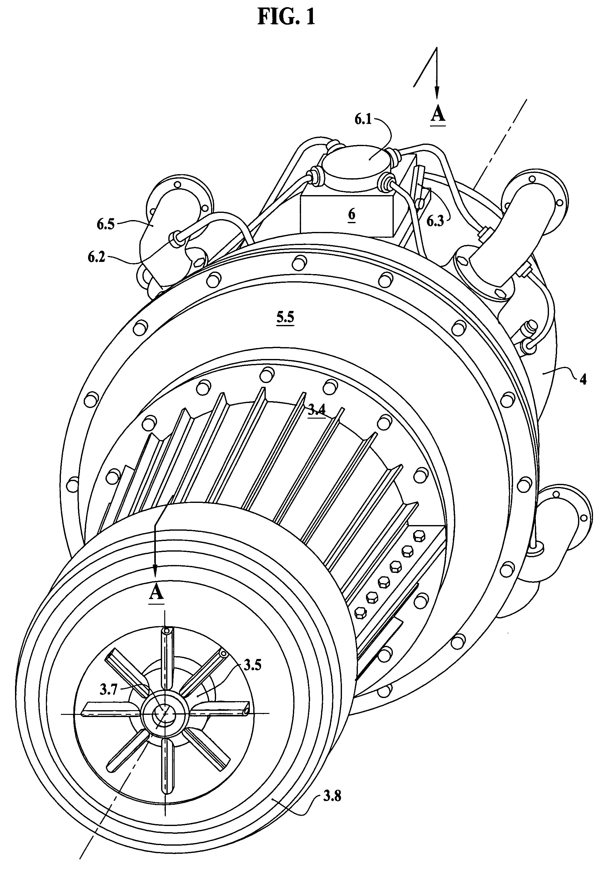
[0025]In FIGS. 1 to 5 there is alone embodiment of a rotary internal combustion engine according to the invention and designated by the reference.

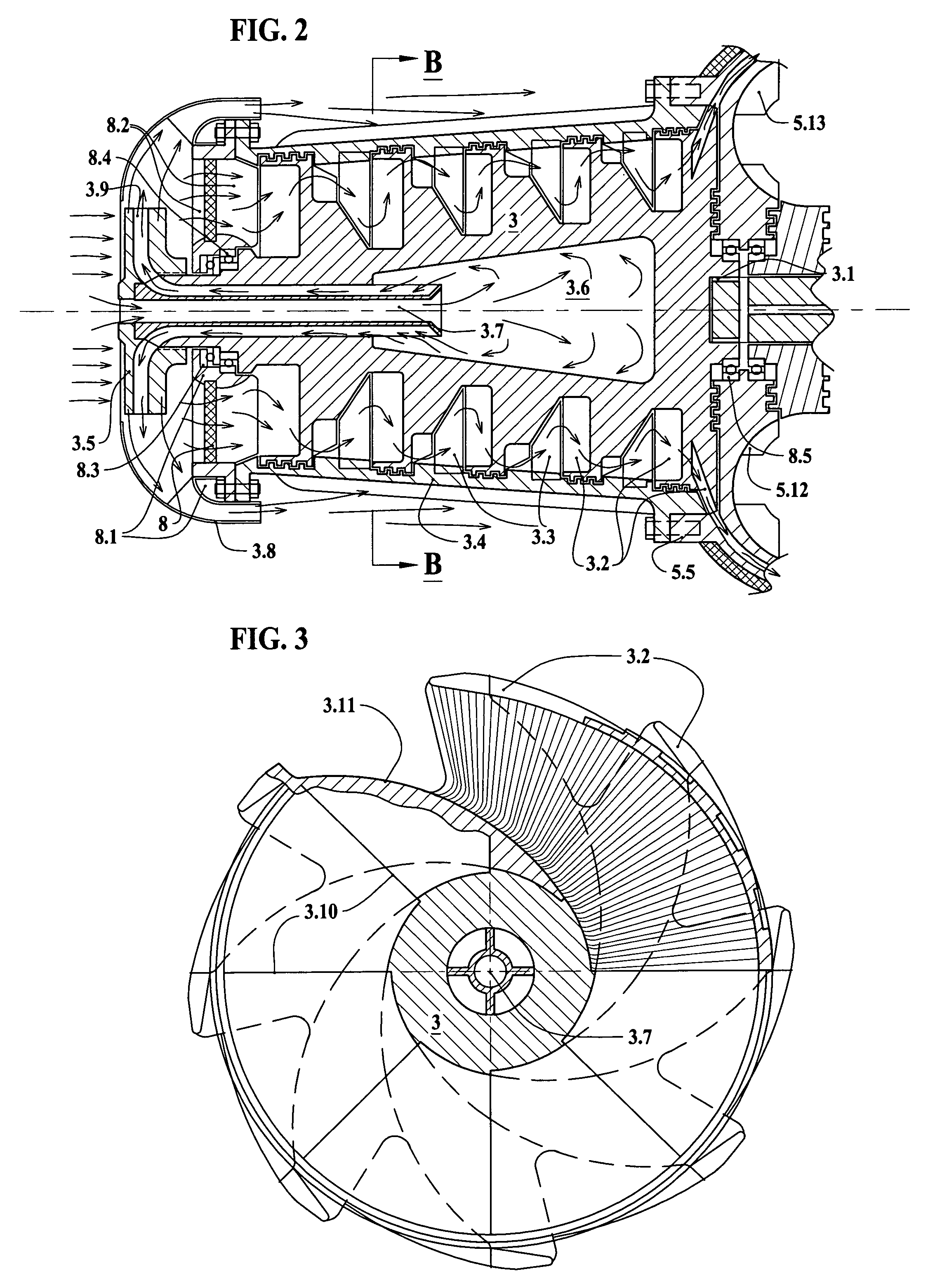
[0026]A hollow impeller 3.5 as shown in FIG. 1 and FIG. 2 consists of the blades, that are twisted so that blades driving air into axial direction by the centrifugal force would throw out heavier than air fractions as dust. Air required for compressor cooling, carrying dust, is directed by a diffuser-shade 3.8 along the cooling blades on the compressor housing 3.4. At the same time said hollow impeller 3.5 with channels in the blades 3.9 sucks air through the outer channels of a cross-pipe 3.7 from the emptiness 3.6, generating vacuum inside of the compression rotor 3. Said hollow impeller 3.5 is mounted onto the front end of the compression rotor 3 so, that channels 3.9 in the blades are joined with the outer channels of a cross-pipe 3.7 located in the center of said compression rotor 3. Ambient air flows through the central channel of a ...


PUM


Abstract

A rotary internal combustion engine with intermittent burning cycle, converting heat energy into the rotary motion, with a multi stage compression rotor (3) and centrifugally-axial air compression impellers (3.2), an air valve (5.1), which alternatively filling up the combustors (4.3) with the compressed air and closing them. A fuel pump (6) compresses fuel and through fuel distributor (6.1) supplies it to the combustors (4.3) to achieve combustion when sprinkled on the hot-red spirals of the ignition plugs (4.5). The gas generated in the combustors (4.3) passes through the cascade turbines (5.10; 5.3; 5.11), driving the power rotor (5) and through the coupling-gear (5.4) transferring rotary motion to a drive shaft (7). A hollow impeller (3.5), mounted onto the compression rotor (3), pumps air through a diffusor-shade (3.8) for cooling the compressor from the outside and the inside.

Description

BACKGROUND OF THE INVENTION[0001]This invention relates to gas turbine engines.[0002]The gas turbine engines, known to the applicant, suffer from the following disadvantages:[0003]1. These engines are not stable, because a gas with higher than 1000 degree C. temperature and a dust inflow with compressed air rapidly destroy high-speed power and compressor turbines. Therefore, for keeping low gas temperature there is a need to supply 3–4 times larger amount of air than it is needed for burning. Attempts to improve air filtering considerably increases the volume of the engine and energy consumption.[0004]2. Low efficiency (only about 30%), because ⅔ of energy generating by the engine is being used for compressing required amount of air.[0005]3. Thermal losses by cooling engine and with hot exhaust are 1.16 times higher than losses in a diesel engine.[0006]4. Bad braking action that is unacceptable for automobiles.[0007]In SU (Russia) patent No 293471 A1 a gas turbine engine is describe...

Claims


Application Information

Patent Timeline
Patent Type & Authority Patents(United States)
IPC IPC(8): F02C5/00F02C5/02F23R7/00F02C5/12F02C6/20F02C7/224F04D29/08F04D29/30F04D29/38
CPCF02C5/02F02C5/12F02C6/20
Inventor STANEVICIUS, ALGIMANTAS ALEKSANDRAS
Owner STANEVICIUS ALGIMANTAS ALEKSANDRAS
Why Eureka
Try Eureka