
Capacitive power equipment medium loss on-line monitoring method and device

A technology for power equipment and dielectric loss, applied in measuring devices, measuring resistance/reactance/impedance, measuring electrical variables, etc., can solve problems such as low automation level, poor digital signal processing capability, and difficulty in filtering out strong electromagnetic interference signals

Inactive Publication Date: 2005-02-16
XI AN JIAOTONG UNIV
View PDF3 Cites 53 Cited by
  • Summary
  • Abstract
  • Description
  • Claims
  • Application Information

AI Technical Summary

Problems solved by technology

Existing electric equipment dielectric loss electrification measurement devices use single-chip microcomputers as the core of calculation and processing, such as Chinese Patent Publication No. 1185585 and Chinese Patent Publication No. 2200823, which are limited by the functions of single-chip microcomputers, resulting in relatively simple functions of the devices without advanced data management capabilities and Remote data query function, while the digital signal processing ability is poor, it is difficult to filter out strong electromagnetic interference signals on site
Chinese Patent Publication No. 1188237 discloses a method and device for measuring the dielectric loss of capacitive electrical equipment with electricity. The device adopts the principle of balanced bridge and combined sampling of capacitance and resistance, which can improve the measurement accuracy, but the device needs to be adjusted manually. Suitable for real-time automatic monitoring
[0004] With the rapid development of the national economy, there is an urgent need to improve the reliability of power operation. In the past, the detection device with single-chip microcomputer as the processing core has simple functions and low automation level, so it is difficult to meet the increasing requirements of the power operation department for equipment automation.

Method used


Image

  • Capacitive power equipment medium loss on-line monitoring method and device
  • Capacitive power equipment medium loss on-line monitoring method and device
  • Capacitive power equipment medium loss on-line monitoring method and device

Examples


Embodiment Construction

[0039] The present invention will be further described in detail below in conjunction with the accompanying drawings.

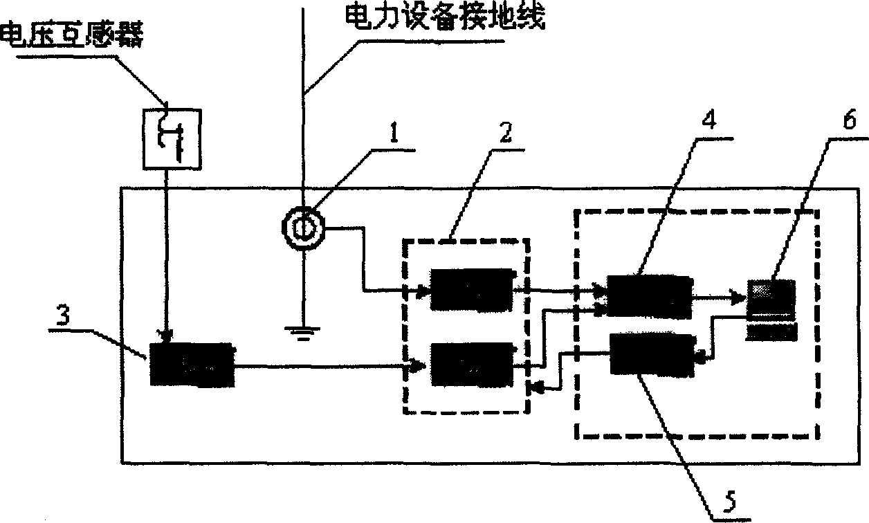
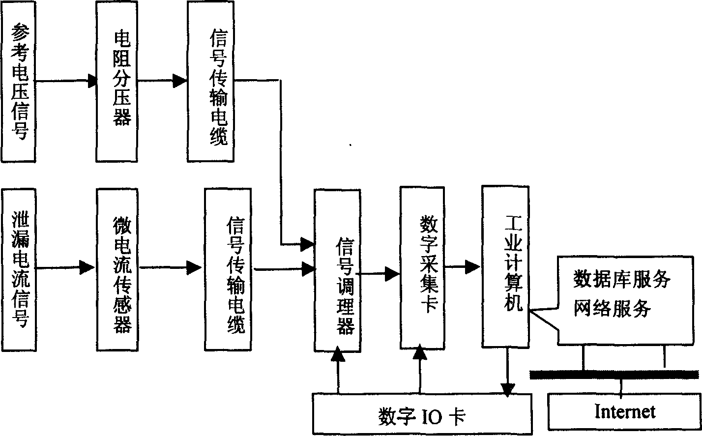
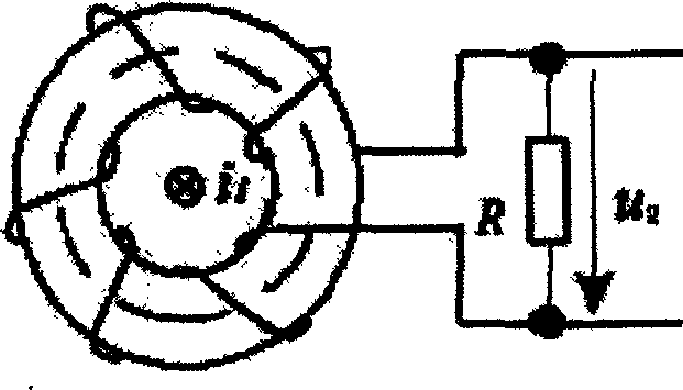
[0040] see figure 2 , according to the technical solution of the present invention, the on-line monitoring method for the dielectric loss of capacitive power equipment adopts a high-precision micro-current sensor connected to the ground wire of the equipment to couple the leakage current signal of the power equipment, and transmits the signal conditioner located in the monitoring room through a signal cable After amplification, filtering, signal isolation, multi-channel selection and other processing, it is sent to the 0 channel of the data acquisition card installed in the computer for acquisition, and at the same time, the reference voltage signal is obtained by using the resistor divider installed at the low-voltage output end of the voltage transformer in the substation After being transmitted by the signal cable, it is sent to the signal conditioner for...


PUM


Abstract

The present invention discloses a method for on-line monitoring dielectric loss of capacitive power equipment and device. It adopts a high-accuracy microcurrent sensor cover-connected on the earthing wire of equipment, and a resistance divider is mounted on the low-voltage output of voltage transformer of transofrmer station, and a computer can be used for making analytical processing and result display so as to implement on-line mointoring of leakage current signal of power equipment. Said device is formed from high-accuracy microcurrent sensor, resistance divide, signal cable, signal modulator, data collecting card, digital I / O card and computer. Said device utilizes ORACLE to implement data management, and has the functions of historical inquiry, report printing, threshold alarm and remote inquiry, etc.

Description

technical field [0001] The invention belongs to the technical field of on-line monitoring of electric power equipment, and relates to a method and a device for on-line monitoring of dielectric loss of capacitive electric equipment. Background technique [0002] With the rapid development of the national economy, the requirements for the reliability of power system operation have been further improved, and the online monitoring technology of power equipment is an important way to improve the reliability of power operation. Capacitive power equipment occupies a large proportion in the power transmission and transformation system, such as transformers, cables, bushings, etc. These power equipment are aging due to factors such as electricity, heat, machinery, and the environment during operation. fall, becoming a potential accident hazard. Dielectric loss is an important insulation index that reflects the insulation status of capacitive power equipment. On-line monitoring of di...

Claims


Application Information

Patent Timeline
IPC IPC(8): G01R27/26
Inventor 成永红陈小林张少锋石山
Owner XI AN JIAOTONG UNIV
Learn More