
Method and system for regulating emissions from idling motor vehicles

a technology for regulating and reducing exhaust emissions, which is applied in the direction of charge feed systems, electrical control, carburettors, etc., to achieve the effect of reducing fuel wastage and greenhouse gas emissions

Inactive Publication Date: 2013-07-09
SPEERS JAMES P +1
View PDF11 Cites 9 Cited by
  • Summary
  • Abstract
  • Description
  • Claims
  • Application Information

AI Technical Summary

Benefits of technology

Reduces fuel wastage and environmental impact by ensuring engines idle only as long as necessary to reach optimal operational conditions, while preventing breaches of anti-idling regulations by automatically shutting down the engine when idling time exceeds set limits.

Problems solved by technology

Once this state has been reached, there is no practical need for the engine to continue idling because further idling is merely wasting fuel and generating more exhaust emissions without enhancing the operational status of the engine appreciably or at all.

Method used


Image

  • Method and system for regulating emissions from idling motor vehicles
  • Method and system for regulating emissions from idling motor vehicles
  • Method and system for regulating emissions from idling motor vehicles

Examples


first embodiment

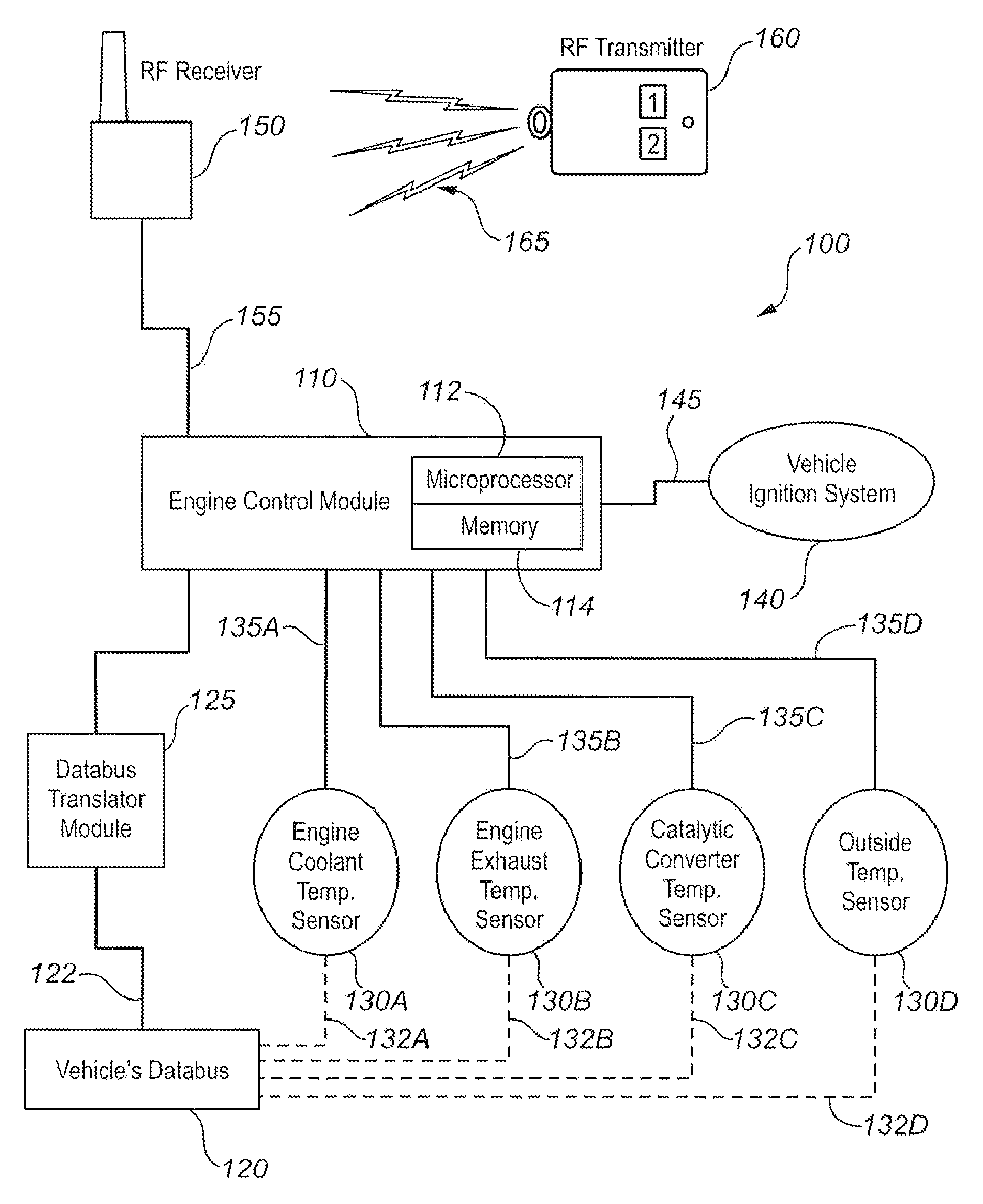
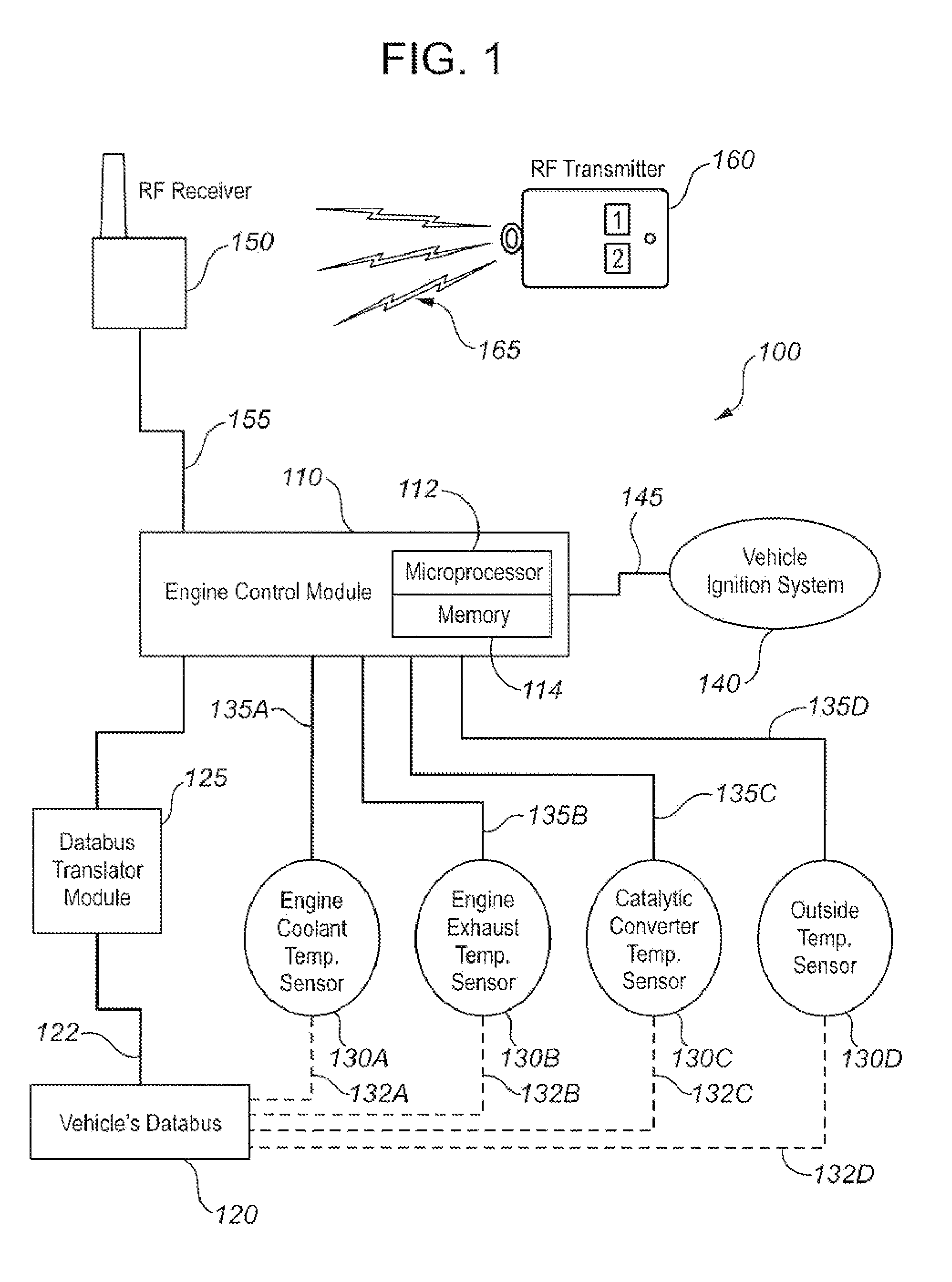
[0027]FIG. 1 schematically illustrates the components of an engine regulation system 100 for regulating motor vehicle exhaust emissions in accordance with the present invention. System 100 comprises engine control module 110 incorporating a microprocessor 112 and a microprocessor memory 114. Control module 110 is in direct electronic communication with one or more sensors 130A, 130B, 130C (and so on), via corresponding sensor data links 135A, 135B, 135C (and so on). Alternatively, control module 110 may be in electronic communication with sensors 135A, 135B, 135C (and so on) via a data bus 120, with which the sensors communicate which via corresponding sensor data links 132A, 132B, 132C (and so on). Sensor data links could be wired or wireless links. Data bus 120 is in communication with control module 110 via a communication link 122 (possibly but not necessarily in association with a data bus translator module 125 as shown in FIG. 1).

[0028]The particular embodiment of system 100 i...

second embodiment

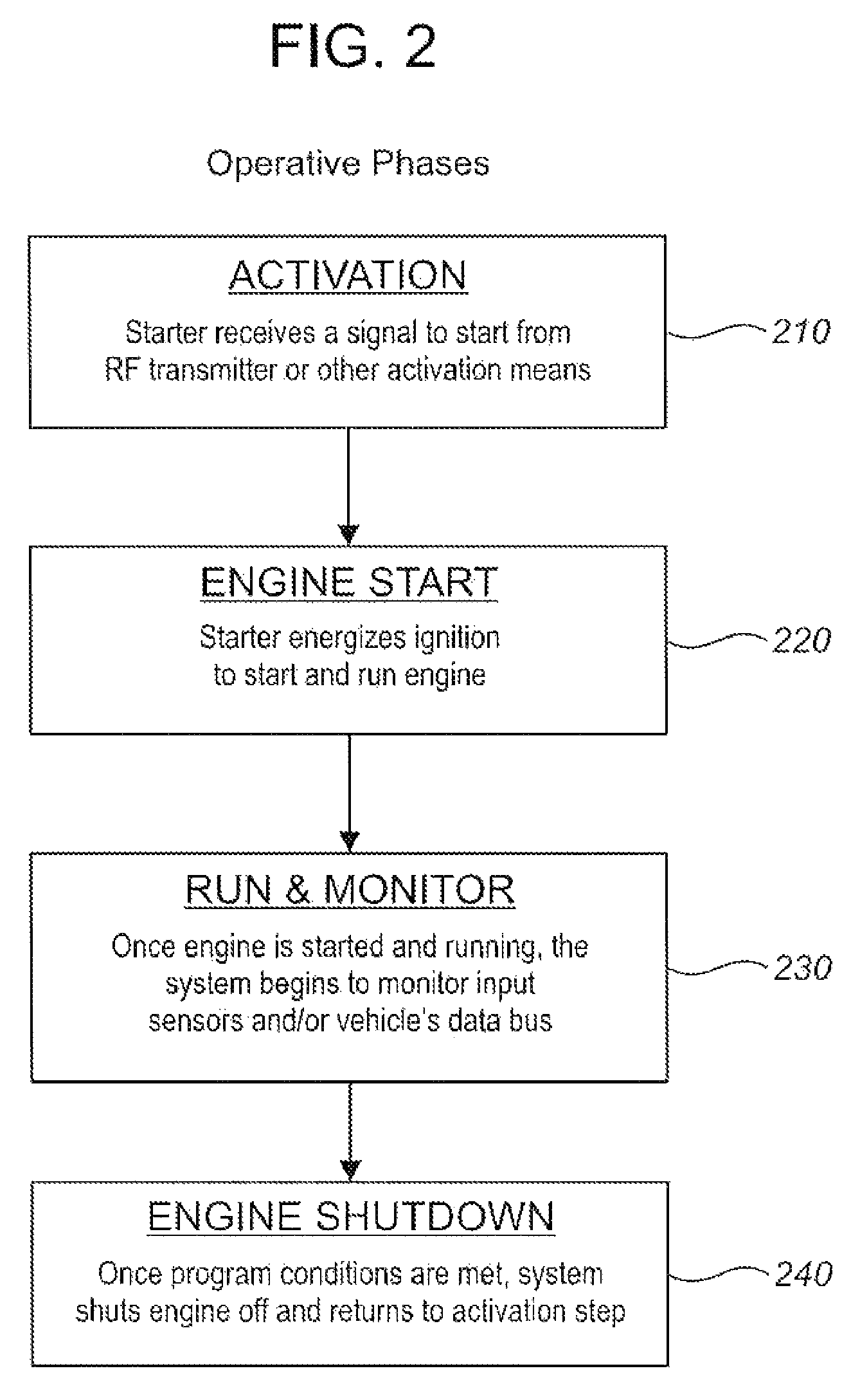
[0031]FIG. 2 is a flow chart schematically illustrating the operative phases of an engine regulation system 100 in accordance the present invention. In the “Activation” phase 210, control module 110 receives a signal from RF transmitter 160 (or other activation means) to initiate start-up of the vehicle's engine. In the “Engine Start” phase 220, control module 110 engages ignition system 140 to start the motor. In the “Run & Monitor” phase 230, which begins as soon as the engine is running, control module 110 monitors “active inputs” from sensors 130A, 130B, etc., and compares these inputs against benchmark values stored in memory 114. Once all monitored active inputs have reached their corresponding benchmark values, microprocessor 112 generates an engine shutdown signal which control module 110 transmits to ignition system 140, which is thereby deactivated and the engine is shut down.

[0032]Engine regulation systems and methods in accordance with the present invention may be adapte...


PUM


Abstract

A system for regulating the operation of an idling motor vehicle monitors one or more selected engine operational parameters such as coolant temperature, exhaust gas temperature, and catalytic converter temperature, and compares the measured parameters against selected benchmark criteria stored in the memory of a microprocessor. The microprocessor controls the vehicle's ignition system to shut down the engine when the measured parameters come within the corresponding benchmark criteria. The system preferably but not necessarily operates in conjunction with a remote vehicle starter system. The system may also or alternatively be adapted to shut down an idling motor vehicle engine when total idling time reaches a specified maximum value, which may be selected based on idling time restriction bylaws. Accordingly, the system promotes reduced fuel consumption and mitigates environmental impacts by automatically regulating vehicle idling times, while also facilitating avoidance of idling time restriction bylaw violations.

Description

CROSS-REFERENCE TO RELATED APPLICATIONS[0001]This application claims the benefit, pursuant to 35 U.S.C. 119(e), of U.S. Provisional Application No. 61 / 148,342, filed on Jan. 29, 2009, and said provisional application is incorporated herein by reference in its entirety to provide continuity of disclosure.FIELD OF THE INVENTION[0002]The present invention relates in general to methods and systems for regulating and reducing exhaust emissions from idling motor vehicles, and in particular to such methods and systems associated with remote motor vehicle starter systems.BACKGROUND OF THE INVENTION[0003]Remote vehicles starters for motor vehicles have been available in the market since the 1980s. A typical conventional remote starter system incorporates a microprocessor pre-programmed to receive RF (i.e., radio frequency) signals from a remote key fob via an internal or external RF circuit. The remote starter system interfaces with a motor vehicle via various transistors, relays, and data o...

Claims


Application Information

Patent Timeline
Patent Type & Authority Patents(United States)
IPC IPC(8): F02D41/08F02D41/00
CPCF02N11/0803F02M3/00F02D41/1446F02D2200/021F02D2200/0802F02N11/0807
Inventor SPEERS, JAMES P.MIN, BYUNG WOO
Owner SPEERS JAMES P
Learn More