Electronic bending endoscope device and endoscope supporting device

a technology of endoscope and supporting device, which is applied in the direction of surgical instrument support, application, instruments, etc., can solve the problems of user burden, large increase in size and weight of operation portion, and difficulty in performing operation

Inactive Publication Date: 2014-08-05
OLYMPUS CORP
View PDF20 Cites 6 Cited by
  • Summary
  • Abstract
  • Description
  • Claims
  • Application Information

AI Technical Summary

Problems solved by technology

Accordingly, the operation portion tends to be largely increased in size and also increased in weight.
Then, when users perform the bending operation using the operation member provided to the operation portion while supporting the operation portion with one hand, the users are tend to be burdened.
This causes difficulties in performing the operation.
Thus, the endoscope supporting device is not appropriate for the use of, for example, housing the endoscope in the supported state or supporting the endoscope in a state just before the start of the use, that is, a so-called usage standby state.
In the method disclosed in the above publication, the work of detaching the endoscope is troublesome.
Further, before an endoscopy is performed, the washed endoscope has to be attached to the supporting device, and this operation is also troublesome.
Moreover, if the endoscope is electrically operated, the endoscope tends to be larger and heavier.
Then, burdens in attaching the endoscope to the supporting device before the endoscopy and in detaching the endoscope after the endoscopy are further increased.
However, such conventional instruments like the hanger are not used when the endoscope or the treatment instruments are being used, but the instruments are configured to store the endoscope or the instruments or to be used in the standby state.

Method used


Image

  • Electronic bending endoscope device and endoscope supporting device
  • Electronic bending endoscope device and endoscope supporting device
  • Electronic bending endoscope device and endoscope supporting device

Examples


Embodiment Construction

[0025]Hereinafter, the invention will be described with reference to illustrated embodiments.

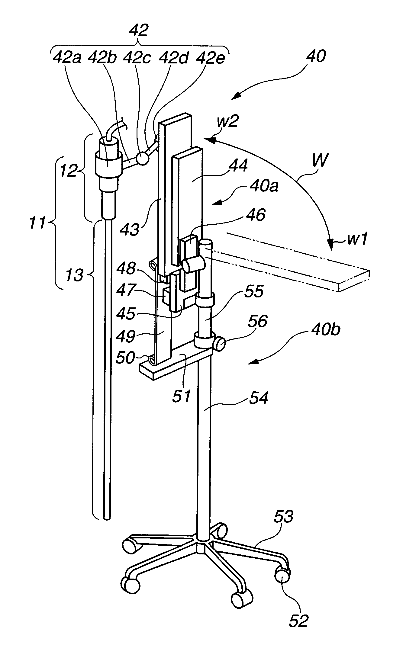
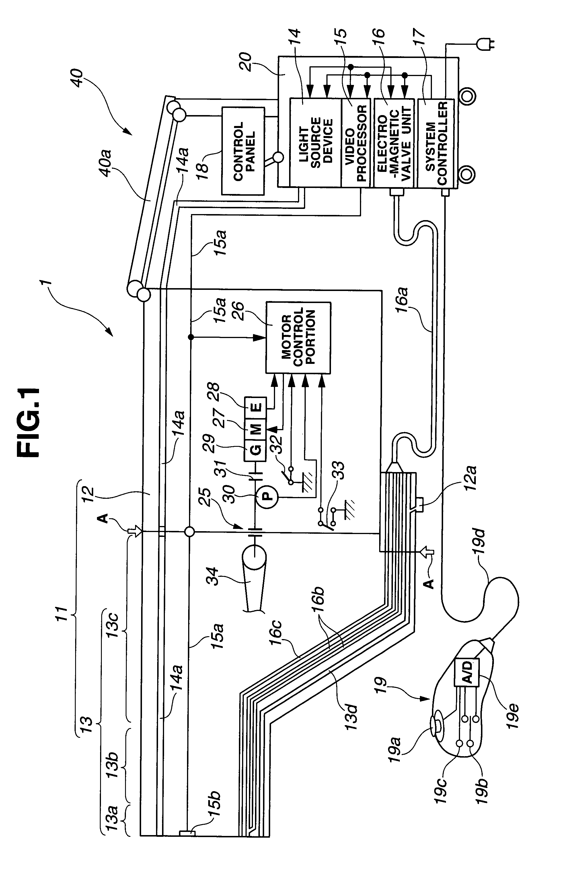
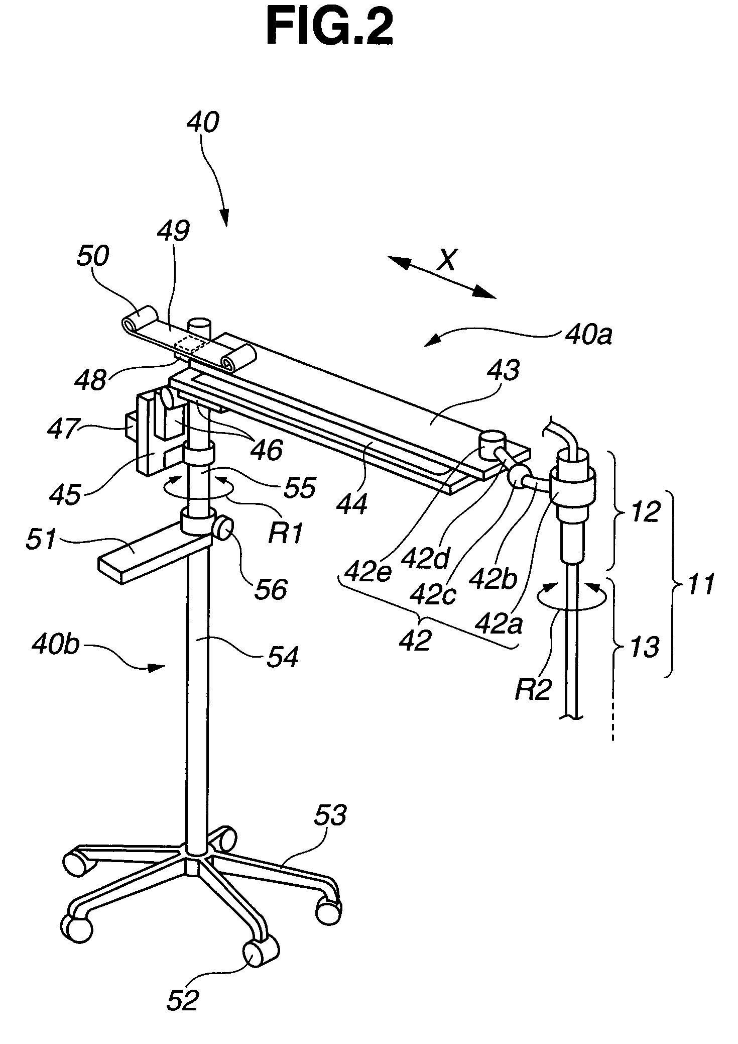
[0026]FIG. 1 is a structural view schematically illustrating a whole structure of an electric bending endoscope device according to an embodiment of the present invention. FIGS. 2 and 3 are outside views illustrating a whole structure of an endoscope supporting device in the electric bending endoscope device according to the present embodiment of the invention. FIG. 2 illustrates a state that the endoscope supporting device is in the usage state. FIG. 3 illustrates a state that the endoscope supporting device is not used (usage standby state). FIGS. 4 to 9 are enlarged views of substantial parts illustrating enlarged parts of the endoscope supporting device of FIGS. 2 and 3. FIG. 4 is a side view illustrating a neighborhood of a bearing portion of a storing portion which is provided at a distal end of the endoscope supporting device of FIGS. 2 and 3 to support the electric bending endoscope ...


PUM


Abstract

The present invention provides an electric bending endoscope device which has an endoscope supporting device. The endoscope supporting device is provided with an electric bending unit and an insertion portion detachably configured in a state that an electric bending endoscope is always supported to improve an efficiency of an operation to be performed before and after an inspection and to reduce the work or burdens of the users, and in the state that the endoscope is being supported, the endoscope can be used, and similarly, the supporting device can be stored in the state that the endoscope is being supported. For the purpose, the electric bending endoscope device includes an endoscope 11 having an observation function and a treatment function of the inside of a body cavity, and an endoscope supporting device 40 having a first moving member (hinge 46) capable of moving up and down the endoscope in a direction perpendicular to a floor, a second moving member (arm movable portion 43 and slide guide 44) capable of moving the endoscope in a horizontal direction with respect to the floor, a first supporting portion (bearing portion 42a) for permitting the endoscope to rotate around an axis and supporting the endoscope, and a second supporting portion (supporting portion 42) for supporting the endoscope movably in vertical and horizontal directions.

Description

TECHNICAL FIELD[0001]The present invention relates to an electric bending endoscope device, and more particularly, the invention relates to an endoscope supporting device which has functions to support and house an electric bending endoscope which electrically drives a bending portion provided in an insertion portion of the endoscope to bend, and relates to an electric bending endoscope device which includes the endoscope supporting device.BACKGROUND ART[0002]Conventionally, endoscopes are widely used, for example, to observe an organ in a body cavity by inserting an elongated insertion portion into the body cavity, or to perform various curative treatments using a treatment instrument which is inserted into a treatment instrument insertion channel if necessary.[0003]Generally, such conventional endoscopes are provided with a bending portion which can be bent in vertical and horizontal directions at a distal end side of an insertion portion. A bending wire extending from an operatio...

Claims


Application Information

Patent Timeline
Patent Type & Authority Patents(United States)
IPC IPC(8): A61B1/04
CPCA61B1/00149A61B1/005G02B7/001G02B23/2476A61B90/50
Inventor KANAZAWA, NORIAKI
Owner OLYMPUS CORP
Why Eureka
Try Eureka