Power transmission line covers and methods and assemblies using same

a technology for power transmission lines and covers, applied in the direction of completely enclosed bus-bar installations, connection contact material, mechanical equipment, etc., can solve the problems of large cost savings for electric power suppliers, potential costly problems, and inability to maintain adequate clearance between conductors and/or other grounded objects

Active Publication Date: 2014-10-14
TYCO ELECTRONICS LOGISTICS AG (CH)
View PDF38 Cites 24 Cited by
  • Summary
  • Abstract
  • Description
  • Claims
  • Application Information

AI Technical Summary

Problems solved by technology

Flashover may result if contact is made between hot conductors or between hot conductors and other grounded objects.
With often hundreds of miles of transmission power lines, the use of uninsulated conductors can result in large cost savings to electric power suppliers.
Although bare conductors may be less expensive to install than insulated conductors, potentially costly problems may arise as a result of their use.
Adequate clearances between conductors and / or other grounded objects may not be sustainable during adverse weather conditions (i.e., storms and high winds).
As a result, the potential for flashover caused by conductors contacting one another or another object may be increased.
In addition, falling trees and tree branches may cause contact between hot conductors and ground, resulting in flashover.
Flashover may result in a power outage which is undesirable to electric power suppliers and to consumers.
Unfortunately, the cost of replacing bare conductors with insulated conductors may be expensive.
Furthermore, an interruption in the delivery of power may be required to replace the conductors.
This may be economically disadvantageous to an electric power supplier as well as being undesirable to electric power consumers.

Method used


Image

  • Power transmission line covers and methods and assemblies using same
  • Power transmission line covers and methods and assemblies using same
  • Power transmission line covers and methods and assemblies using same

Examples


Embodiment Construction

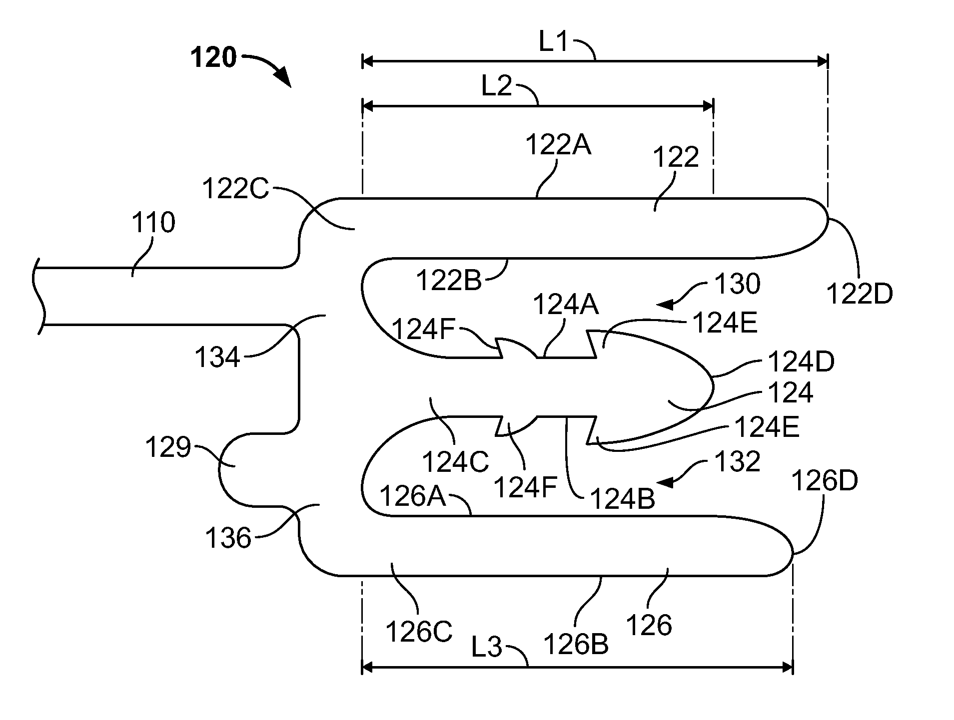
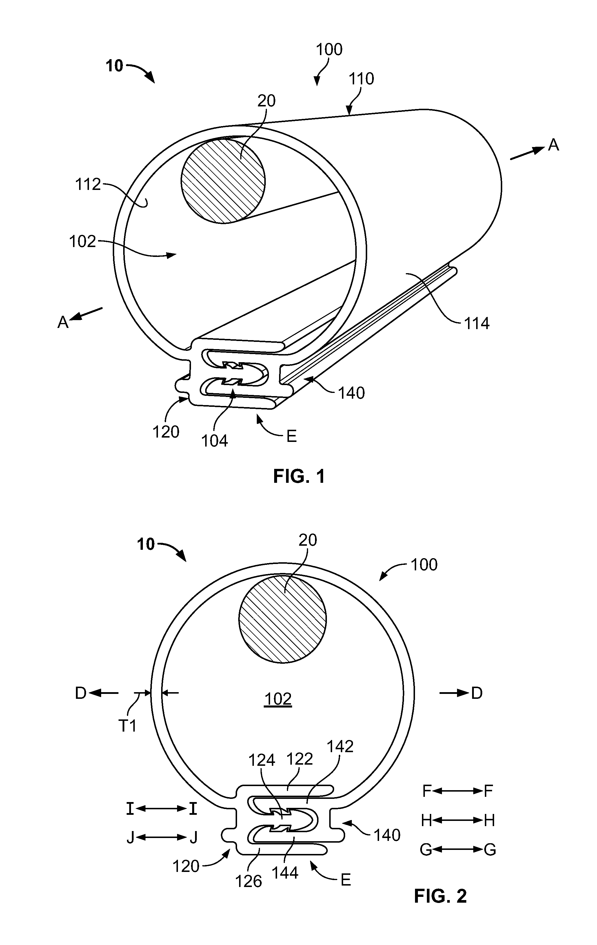
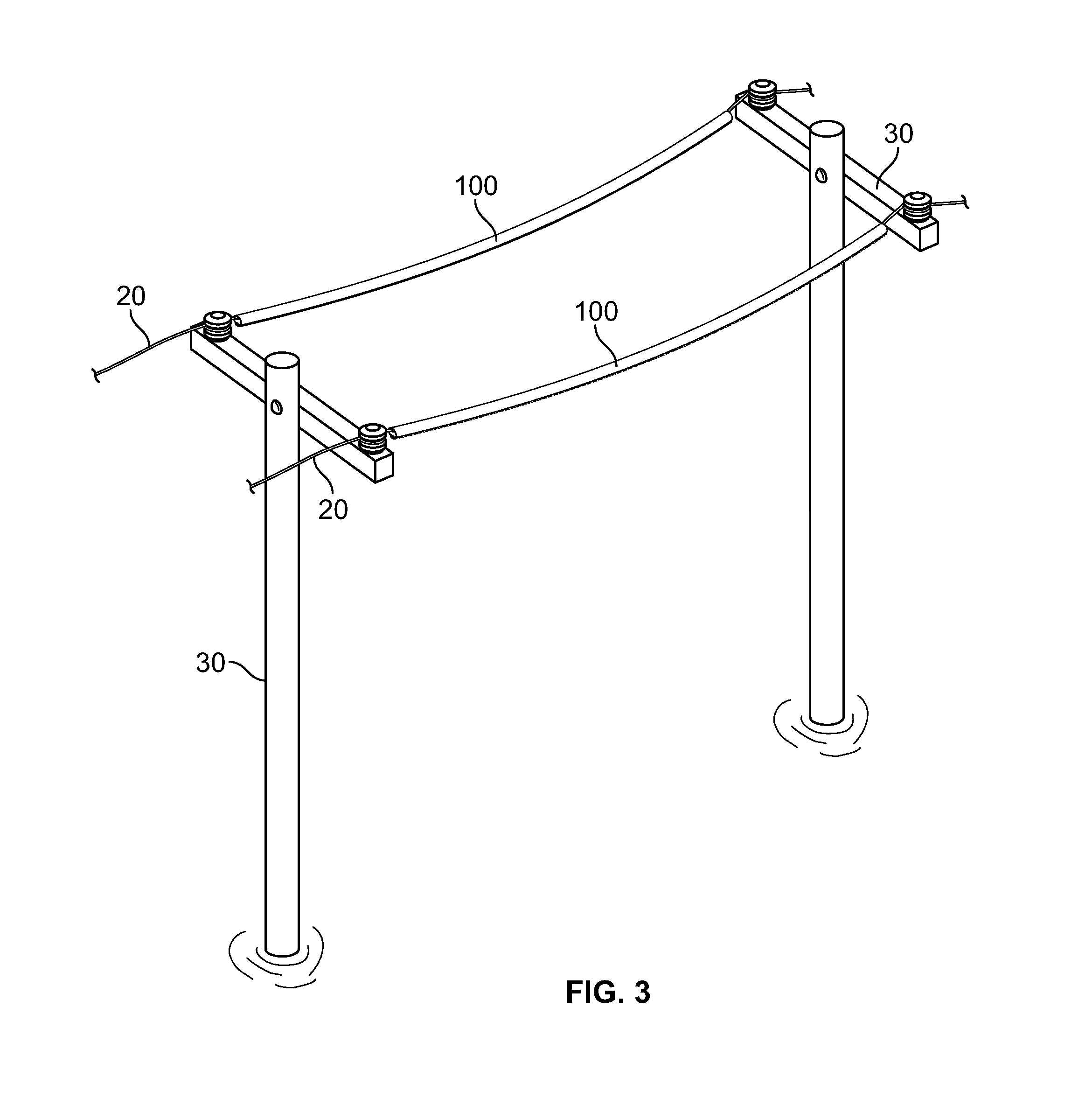
[0018]The present invention now will be described more fully hereinafter with reference to the accompanying drawings, in which illustrative embodiments of the invention are shown. In the drawings, the relative sizes of regions or features may be exaggerated for clarity. This invention may, however, be embodied in many different forms and should not be construed as limited to the embodiments set forth herein; rather, these embodiments are provided so that this disclosure will be thorough and complete, and will fully convey the scope of the invention to those skilled in the art.

[0019]It will be understood that, although the terms first, second, etc. may be used herein to describe various elements, components, regions, layers and / or sections, these elements, components, regions, layers and / or sections should not be limited by these terms. These terms are only used to distinguish one element, component, region, layer or section from another region, layer or section. Thus, a first elemen...


PUM

PropertyMeasurementUnit
dielectric strengthaaaaaaaaaa
voltageaaaaaaaaaa
thickness T1aaaaaaaaaa

Abstract

A power transmission line cover includes an elongate, flexible panel and first and second elongate, integral edge portions. The first edge portion includes an elongate first latch feature and the second edge portion includes an elongate second latch feature. The cover includes an elongate inner creepage extender wall forming a part of one of the first and second edge portions, and an elongate outer creepage extender wall forming a part of one of the first and second edge portions. The flexible panel is wrapped about a power line and the edge portions are joined together to form a longitudinally extending closure seam wherein the latch features are coupled and the edge portions form an electrical creepage path extending from the chamber to an exterior boundary of the cover along the inner creepage extender wall, between the first and second latch features, and along the outer creepage extender wall.

Description

FIELD OF THE INVENTION[0001]The present invention relates generally to insulating covers and, more particularly, to insulating covers for power transmission lines.BACKGROUND OF THE INVENTION[0002]Electrical power may be transmitted from a generation source to consumers via overhead conductors strung between towers or poles. Electrical power is typically transmitted in phases wherein multiple conductors are utilized. One or more of these conductors are “hot” conductors carrying a specified amount of alternating current electric power and one conductor serves as a ground. Flashover may result if contact is made between hot conductors or between hot conductors and other grounded objects. Non-grounded contact with a hot conductor, such as when a bird sits upon a hot conductor, typically does not result in flashover.[0003]Because uninsulated conductors are typically less expensive than insulated conductors, many electric power suppliers utilize uninsulated conductors for power transmissi...

Claims


Application Information

Patent Timeline
Patent Type & Authority Patents(United States)
IPC IPC(8): H02G3/14
CPCH02G3/0481H02G7/00Y10T29/4987
Inventor FRYE, TERRY, EDWARD
Owner TYCO ELECTRONICS LOGISTICS AG (CH)
Why Eureka
Try Eureka