Two-stroke engine

a two-stroke engine technology, applied in the direction of combustion engines, machines/engines, valve arrangements, etc., can solve problems such as engine stall, and achieve the effects of reducing the amount of constructive space, simple configuration, and simple configuration

Active Publication Date: 2014-11-11
ANDREAS STIHL AG & CO KG
View PDF2 Cites 3 Cited by
  • Summary
  • Abstract
  • Description
  • Claims
  • Application Information

AI Technical Summary

Benefits of technology

[0004]It is an object of the present invention to provide a two-stroke engine of the aforementioned kind that even for decreasing engine speed under load has a stable running behavior. A further object of the invention is to provide a hand-held power tool whose two-stroke engine exhibits a stable running behavior.

Problems solved by technology

When the engine speed at full throttle decreases as a result of increasing load, the supplied fuel quantity can become too small causing the engine to stall.

Method used


Image

  • Two-stroke engine
  • Two-stroke engine
  • Two-stroke engine

Examples


Embodiment Construction

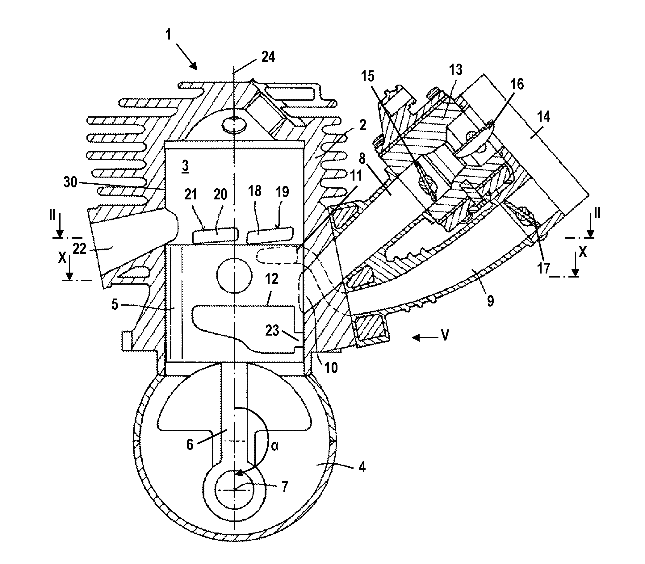
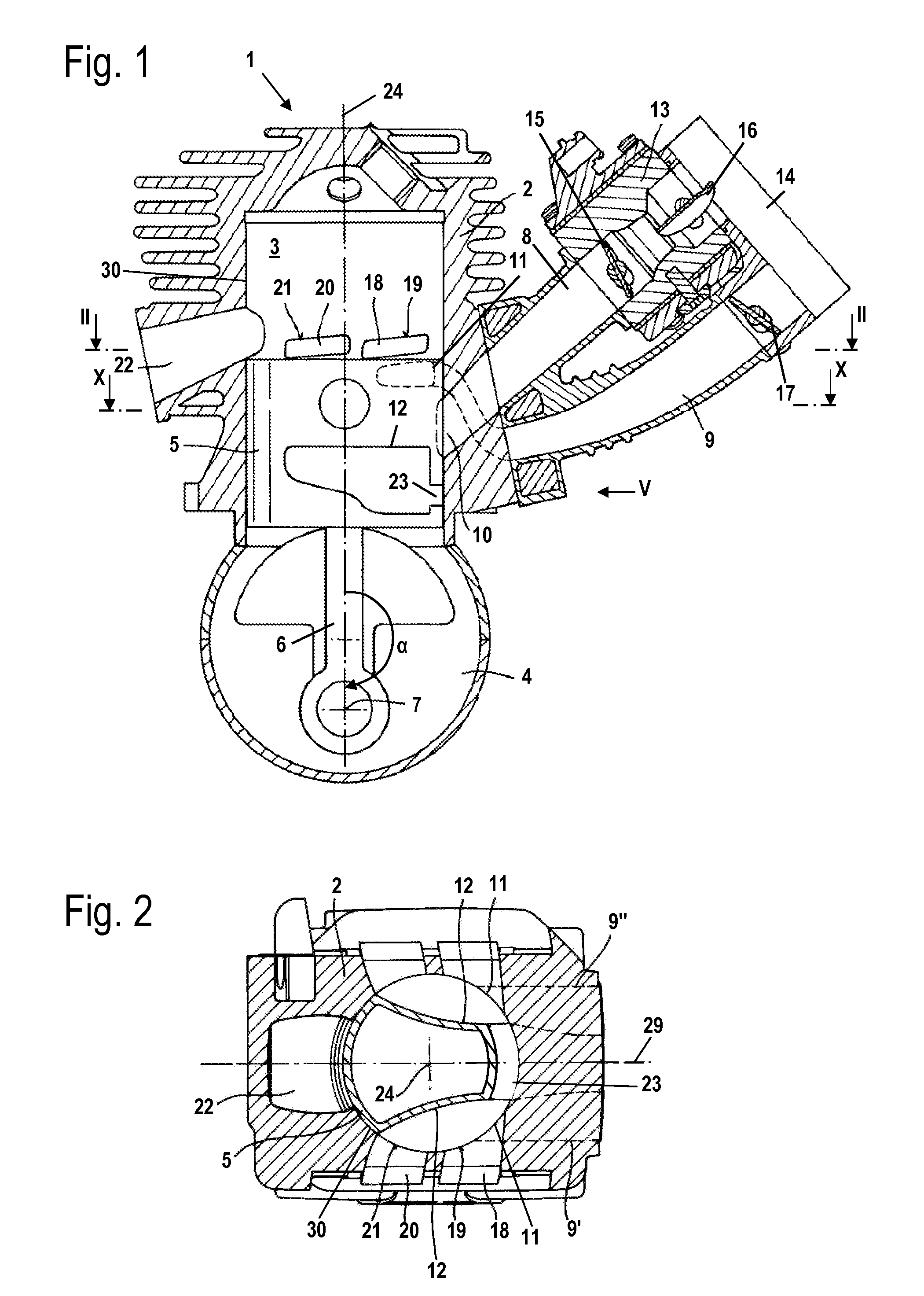
[0029]FIG. 1 shows a two-stroke engine 1 that is operating with scavenging air and is embodied as a single cylinder engine. The engine may be advantageously provided as a drive motor of a hand-held power tool such as a motor chainsaw, a cut-off machine, a trimmer, a lawnmower or the like. The two-stroke engine 1 has a cylinder 2 in which a combustion chamber 3 is formed. The combustion chamber 3 is delimited by a piston 5 that is supported reciprocatingly within the cylinder 2 and, by means of a connecting rod 6, is driving a crankshaft 7 rotatably supported in the crankcase 4. At the cylinder bore 30 of the cylinder 2 a mixture passage 8 opens by means of a mixture inlet 10 that is piston-controlled by piston 5. The two-stroke engine 1 has an air passage 9 that is divided in the area of the cylinder 2 into the two branches 9′ and 9″ (FIG. 2). Each branch 9′, 9″ of the air passage 9 opens with an air inlet 11 at the cylinder bore 30. An outlet 22 communicates with the combustion cha...


PUM


Abstract

A two-stroke engine has a cylinder having a cylinder bore with a combustion chamber and an outlet connected with the combustion chamber. A piston is disposed in the cylinder and delimits the combustion chamber. The piston has a piston recess. A crankcase is provided that has a crankshaft rotatably supported therein. The piston drives in rotation the crankshaft. In at least one position of the piston, the crankcase is connected by a transfer passage with the combustion chamber. An air passage is provided as well as a mixture passage that has a mixture inlet that is disposed at the cylinder bore and opens into the cylinder bore and is piston-controlled. The transfer passage is connected by the piston recess to the air passage when the piston is at top dead center. The piston recess has a connection to the mixture inlet in at least one position of the piston.

Description

BACKGROUND OF THE INVENTION[0001]The invention relates to a two-stroke engine comprising a cylinder with a combustion chamber provided therein that is delimited by a piston. The piston drives in rotation a crankshaft that is rotatably supported in a crankcase. In at least one position of the piston, the crankcase is connected by means of at least one transfer passage with the combustion chamber. An outlet is provided at the combustion chamber. An air passage is provided as well as a mixture passage that opens with a mixture inlet into the cylinder bore and is piston-controlled by the piston. The transfer passage is connected in the area of top dead center of the piston by means of a piston recess to the air passage. The invention further relates to a hand-held power tool with such an engine.[0002]U.S. Pat. No. 7,082,910 B2 discloses a two-stroke engine comprising an air passage and a mixture passage. By means of the air passage scavenging air is supplied to the transfer passages thr...

Claims


Application Information

Patent Timeline
Patent Type & Authority Patents(United States)
IPC IPC(8): F02B17/00F02B3/00F01L5/06F02B25/22F02B25/14F02B33/04F02B1/00F02B75/02
CPCF02B2075/027F02B1/00F02B25/22F02B17/00F02B33/04F02B3/00F01L5/06F02B25/14
Inventor KUNERT, NIELS
Owner ANDREAS STIHL AG & CO KG
Why Eureka
Try Eureka