Optical scanner and imaging apparatus

a scanning and optical technology, applied in the field of optical scanners, can solve the problems of limited downsizing of the actuator and a device mounted with the actuator, unstable operation of the actuator, and unstable common electrodes, so as to reduce the number of electrical wirings, maintain the stability of the operation, and reduce the size of the entire apparatus

Active Publication Date: 2019-07-04
HITACHI LTD
View PDF0 Cites 0 Cited by
  • Summary
  • Abstract
  • Description
  • Claims
  • Application Information

AI Technical Summary

Benefits of technology

[0007]According to the invention, it is possible to provide an optical scanner capable of reducing the number of electrical wirings while maintaining stability of an operation and downsizing the entire apparatus.

Problems solved by technology

For this reason, a thickness of a wiring included in the actuator and a joining portion become large, and thus downsizing of the actuator and a device mounted with the actuator is limited.
Meanwhile, when a wiring for ground connection of the common electrode is eliminated, a potential of the common electrode becomes unstable, and thus an operation of the actuator becomes unstable.

Method used


Image

  • Optical scanner and imaging apparatus
  • Optical scanner and imaging apparatus
  • Optical scanner and imaging apparatus

Examples


embodiment 1

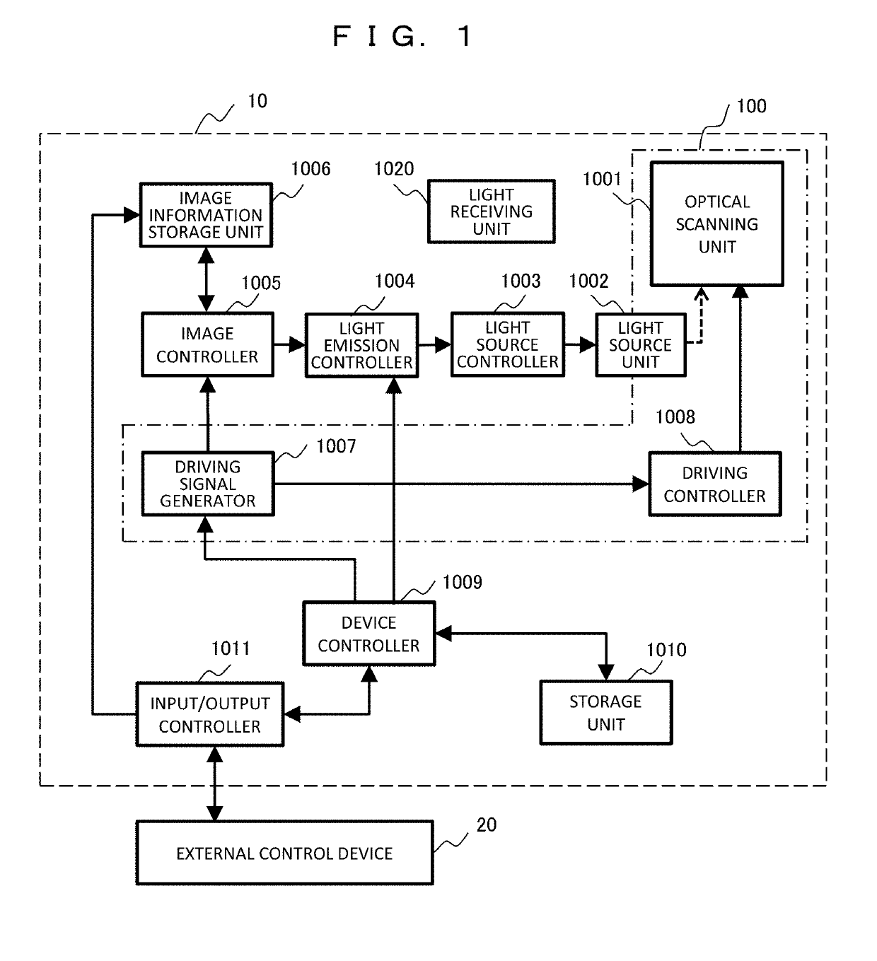
[0027]FIG. 1 is a block diagram illustrating a configuration of an imaging apparatus 10 according to Embodiment 1. For example, the imaging apparatus 10 is an apparatus that projects an image such as a projector or a head mounted display, and includes an optical scanner 100 that scans image light on a projection surface.

[0028]The imaging apparatus 10 includes an optical scanning unit 1001, a light source unit 1002, a light source controller 1003, a light emission controller 1004, an image controller 1005, an image information storage unit 1006, a driving signal generator 1007, a driving controller 1008, a device controller 1009, a storage unit 1010, an input / output controller 1011, and a light receiving unit 1020. Among these units, the optical scanning unit 1001, and the driving signal generator 1007 and the driving controller 1008 driving the optical scanning unit 1001 are included in the optical scanner 100. Incidentally, the optical scanner 100 may include another element such a...

embodiment 2

[0074]In Embodiment 1, all the impedances of the four piezoelectric elements are equal to each other. However, in practice, the impedances may not coincide with each other due to a manufacturing variation, etc. Therefore, Embodiment 2 adopts a configuration in which a driving signal is corrected in accordance with an impedance difference.

[0075]FIG. 9 is a block diagram illustrating a configuration of an imaging apparatus 10 according to Embodiment 2. The apparatus is configured such that a driving signal correction unit 1012 is added to the basic configuration of Embodiment 1 (FIG. 1).

[0076]The driving signal correction unit 1012 corrects a driving signal according to minute differences in the impedances of the four piezoelectric elements included in the vibration portion 101. That is, a driving signal obtained by correcting the amplitude of the driving signal generated by the driving signal generator 1007 is supplied to the driving controller 1008. Hereinafter, a description will b...

embodiment 3

[0083]In Embodiment 1, the waveform of the driving signal of the piezoelectric element has a sinusoidal shape. However, in Embodiment 3, a pulse-like driving signal is used.

[0084]FIG. 11 is a block diagram illustrating a configuration of an imaging apparatus 10 according to Embodiment 3. The apparatus is configured such that a driving pulse generator 1017 and a driving controller 1018 replace corresponding units of the basic configuration of Embodiment 1 (FIG. 1). The driving pulse generator 1017 generates a driving pulse as a driving signal, and the driving controller 1018 applies a drive voltage to the optical scanning unit 1001 (the vibration portion 101) based thereon.

[0085]FIGS. 12A-12B are diagrams illustrating a configuration example of the driving controller 1018. Here, a gate circuit such as an H bridge circuit is used. As a switching element, FIG. 12A uses a MOSFET and FIG. 12B uses a transistor. Here, a driving circuit in which a voltage is applied to the pair of piezoele...


PUM


Abstract

In an optical scanner 100, a vibration portion 101 includes first and third elements 3021 and 3023 that vibrate a light guide path 102 in a direction substantially perpendicular to an optical axis direction, and second and fourth elements 3022 and 3024 that vibrate the light guide path in a direction substantially perpendicular to a vibration direction thereof. A driving signal is applied to each of electrodes 3011 to 3014, each of which corresponds to one electrode of each of the first to fourth elements, and the other electrode 3015 is used as a common electrode having a floating potential. A driving signal generator 1007 generates a driving signal such that a median value of driving signals Vy1and Vy2 applied to the first and third elements and a median value of driving signals Vx1 and Vx2 applied to the second and fourth elements correspond to substantially the same value.

Description

CLAIM OF PRIORITY[0001]The present application claims priority from Japanese patent application serial No. JP 2017-253447, filed on Dec. 28, 2017, the content of which is hereby incorporated by reference into this application.BACKGROUND OF THE INVENTION(1) Field of the Invention[0002]The present invention relates to an optical scanner that scans light by a vibration portion of a piezoelectric element, etc. and an imaging apparatus using the same.(2) Description of the Related Art[0003]As a technology for scanning light by a vibration portion, JP 2014-180317 A discloses an optical fiber scanner in which a vibration damping member is disposed between a vibration generator and an emission end to allow uniform vibration of an optical fiber. JP 2009-192252 A discloses a configuration in which an outer peripheral surface is covered with a single strip electrode, the electrode is connected to a ground potential, and a voltage is applied to a divided electrode on an inner peripheral surface...

Claims


Application Information

Patent Timeline
Patent Type & Authority Applications(United States)
IPC IPC(8): G02B26/10G02B26/08
CPCG02B26/101G02B26/0858H01L41/092G02B26/103H02N2/028H10N30/206H10N30/2027
Inventor MATSUDA, TAKAHIROSEO, YOSHIHOOUCHI, SATOSHIONOE, SHINSUKE
Owner HITACHI LTD
Why Eureka
Try Eureka