Power generating windbags and waterbags

a technology of windbags and waterbags, which is applied in the direction of renewable energy generation, electric generator control, greenhouse gas reduction, etc., can solve the problems of deficiency and self-limiting of devices such as water wheels, windmills, wind turbines,

Active Publication Date: 2015-02-24
SIA YIK HEI
View PDF29 Cites 18 Cited by
  • Summary
  • Abstract
  • Description
  • Claims
  • Application Information

AI Technical Summary

Benefits of technology

[0006]Present invention discloses a method, system, equipment, apparatus, techniques and ecosystem for generating electrical power, comprising of: a power-bag mounted on a mobile navigable vehicle body pulling a tether (drive unit 51) attached to an electricity generation module (driven unit 55). Such a dynamic method of power generation utilizes a vehicle mounted bag to capture and entrap motive fluid comprising wind and / or water; the moving fluid medium propelling the trapping bag and vehicle body along in the linear direction of its flow; with the tether powering the generation module to produce electricity for the duration of the entire journey. In the wind-borne form this apparatus may be configured as a Hybrid Aerial Vehicle (HAV-100); while in the waterborne form the apparatus may be customized as a Hybrid Underwater Vehicle (HUV-200). Equipment, apparatus and an ecosystem for operating the hybrid vehicle may be mounted on and borne by the vehicle body, including: flight control surfaces, tether lines, bridle lines, retract lines, winches, navigator-capsule, motorized turbo-fans, propellers, side-thrusters, batteries, engines, compressed air-tanks, fuel tanks, balloons, etc. Enabling capabilities includes: different methods of depowering the HAV-100 and HUV-200; safety features; station hopping; adding of new tether spools 52 to running spools 52; extending the range and power-run of the drive units 51.
[0007]To this end present invention provides a method wherein the mass movement of fluid medium comprising wind 10 and / or water 20 may be harnessed in a systematic manner by means of a bagged power generation system. The two components may comprise of: (1) a windborne; (2) a marine-waterborne component. Wind power by means of: large singular bags 30; integrated hybrid balloon-bag apparatus 60; a plurality of bags 30 spearheaded by an unmanned aerial vehicle 80; “Hybrid Bagtoons 60” comprising bags 30 integrated with bodies of LTA gas and engine driven turbo-fans 70; HAVs-100 comprising bags 30 mounted on cylindrically-shaped-inflatable (balloon) “rocket-like” body filled with a lighter-than-air gas and / or powered by engine driven turbo-fans 70; “Morphing Bag-crafts 90” which transforms into huge windbags. Water power by means of: large singular bags 40; hybrid water-bags 210 integrated with balloons 202, UUVs 230 and submarine-boats 220; a plurality of water-bags 40 spearheaded by an unmanned underwater vehicle 230; HUVs-200 comprising water-bag 40 mounted on a cylindrically-shaped “torpedo-like” body 201 filled with water, air, and / or driven by propellers 240; power bags 40 running along designated wire-line-guided routes / or paths. The bagged power generation system may be used in a broad range of terrain and environment comprising: free flowing airborne and / or waterborne apparatus; and wire-line guided routes; from surface to high altitude; from a surface platform towards a surface platform; from a fixed surface platform (upstream) towards a fixed / or mobile subsea platform (downstream); from a fixed / or mobile submerged subsea platform (upstream) to a fixed / or mobile subsea platform (downstream); subsea to subsea / or surface production platforms. The HAVs-100 and HUVs-200 travelling in a horizontal or inclined path; cutting through different strata(s): from surface to high altitude; from surface to deep-sea bottom—going where the wind blows; going where the water flows! The structural configuration for the wire-guided bags may comprise: horizontally disposed; and vertically inclined. Such that the dynamic forces in motion may be harvested more effectively; because even though wind and water may move in a linear, uni-directional manner most of the time; their movement may be inclined. Spaced at regular intervals, multiple bags may be put in power run phase along the guide-lines / or guide-wires at any given point in time. Parallel lines of bags may be arranged horizontally; such that layers upon layers of such lines of bags may also be configured vertically, one horizontal layer arranged on top of another layer. Wherein lines upon lines, tiers upon tiers comprising a multitude of such running power bags may be arranged in proximity, configured to generate a continuous supply of electrical power. Maximizing bagged fluid volume and contact time for the capture, entrapment, partial encapsulation and extraction of the kinetic energy of marine current 20. Such a superior structural configuration maximizes and optimizes productivity and efficiency of the marine hydro-energy-farm in harnessing the sustainable “green” energies of mother-nature effectively and systematically. The airborne platform for wire line guided bags 30, HAV-100 may comprise of highly specialized equipment such as HAV-45; and the Unmanned Aircraft System (UAS) infrastructure.
[0008]When we see an empty plastic bag being blown away by a strong gust of wind, we'd say: “the bag flew in the air.” In appearance, visual illusion and mental perception, we may equate the bag as being capable of aerial flight. But in actual fact the bag does not fly; in the real sense of the word “flying” because it is not capable of generating aerodynamic lift. But due to its light weight and large empty cavity, the bag captures and entraps moving air; and is easily carried along, swept away by the moving air current we called “wind.” The working principal of an air-bag / or windbag 30 lies in entrapping, capturing and partially encapsulating wind; and got carried along in the direction of the current flow. The airborne windbags system of power generation is more complicated and entails more expensive customized equipment comprising of the UAS infrastructure such as: Hybrid Aerial Vehicles HAV-100, “Morphing Bag-crafts 90,” etc. than the parallel seaborne water-bags system of power generation. Due to the fact that water is 829 times denser than air, water based generation systems may float in the fluid medium by means of encapsulated air; attached floatation devices; weighted down by means of sinkers, weights; secured to subsea piles; mooring points affixed onto the sea bed using suction cups. Equipment used may comprise reconfigured vessels used in the oil and gas exploration and production industry such as: fixed platforms, mobile jack-up rigs; semi-submersible rigs, support ships, floating production storage offloading (FPSO) vessels, etc.

Problems solved by technology

However, some devices like: wind mills, wind turbines, water wheels may be deficient and self-limiting due to (i) the minimized surface area for capture of the kinetic energy of the fluid medium as evidenced by the limited size and number of turbine blades, rotors, propellers, spokes; sails, etc. that may be affixed to an apparatus; (ii) the extremely short, momentary, contact time between the drive surface and the moving fluid medium providing the kinetic energy lasting a few seconds; and (iii) harnessing the kinetic energy in an ad-hoc randomized manner.
But in actual fact the bag does not fly; in the real sense of the word “flying” because it is not capable of generating aerodynamic lift.
The airborne windbags system of power generation is more complicated and entails more expensive customized equipment comprising of the UAS infrastructure such as: Hybrid Aerial Vehicles HAV-100, “Morphing Bag-crafts 90,” etc. than the parallel seaborne water-bags system of power generation.

Method used


Image

  • Power generating windbags and waterbags
  • Power generating windbags and waterbags
  • Power generating windbags and waterbags

Examples


Embodiment Construction

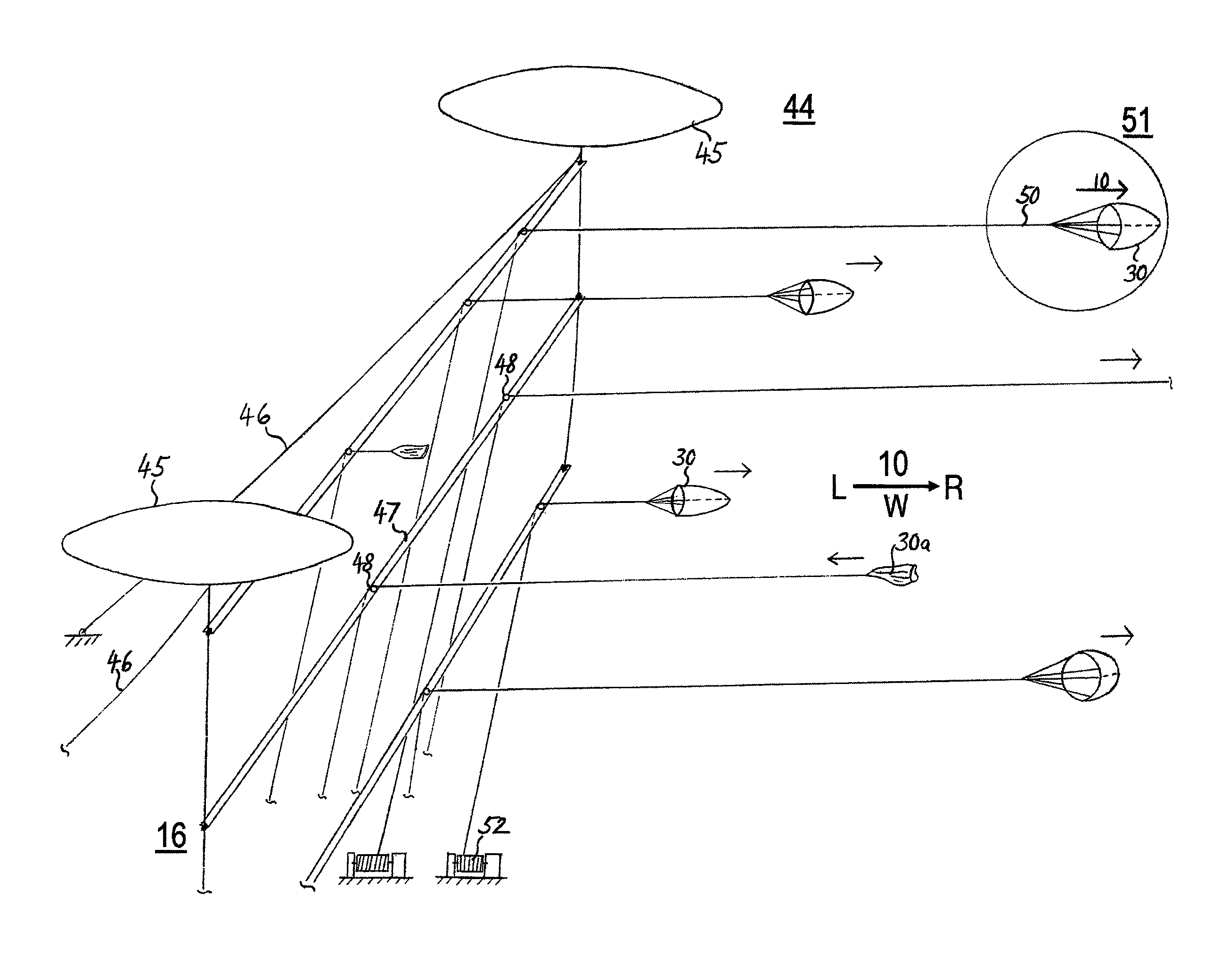
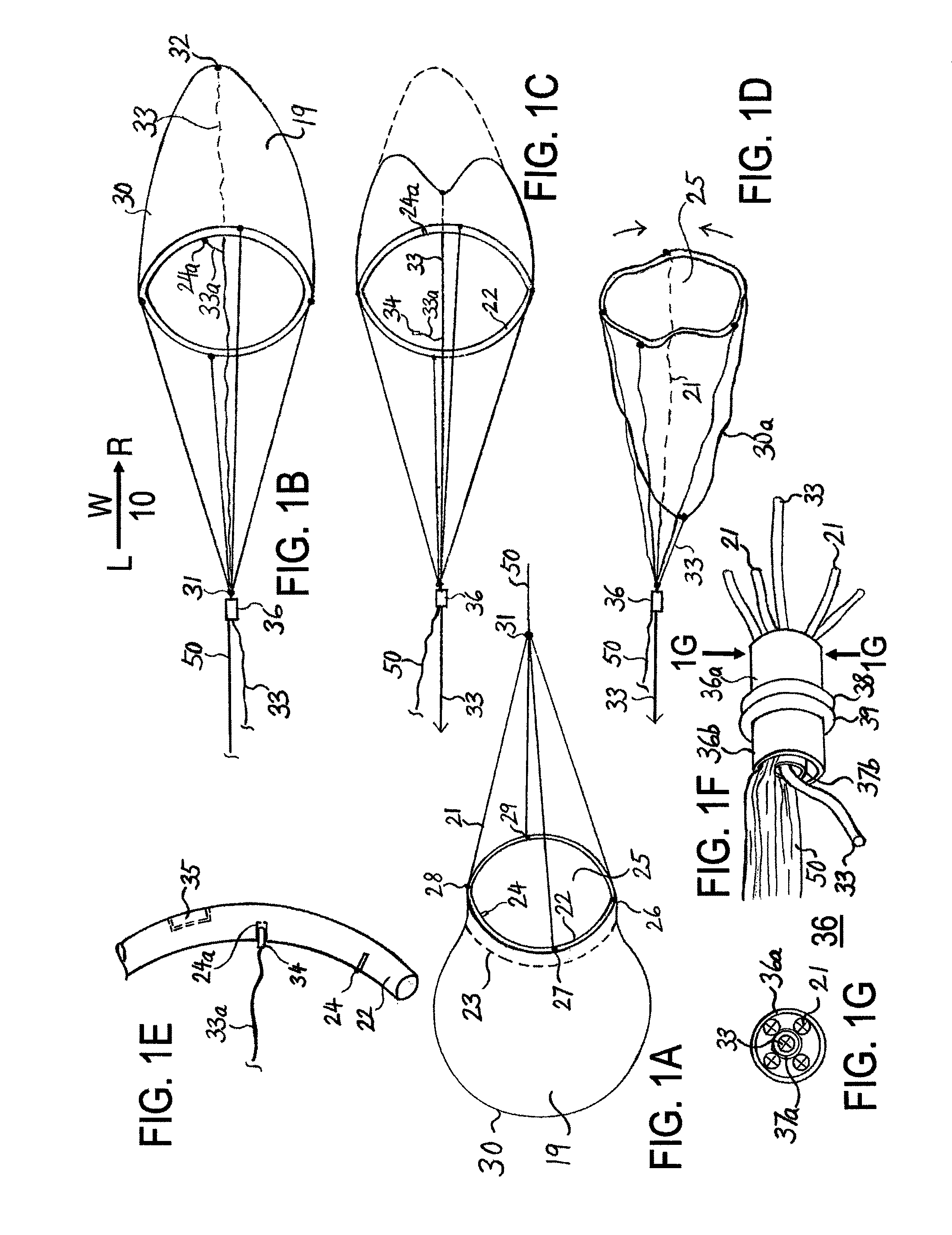
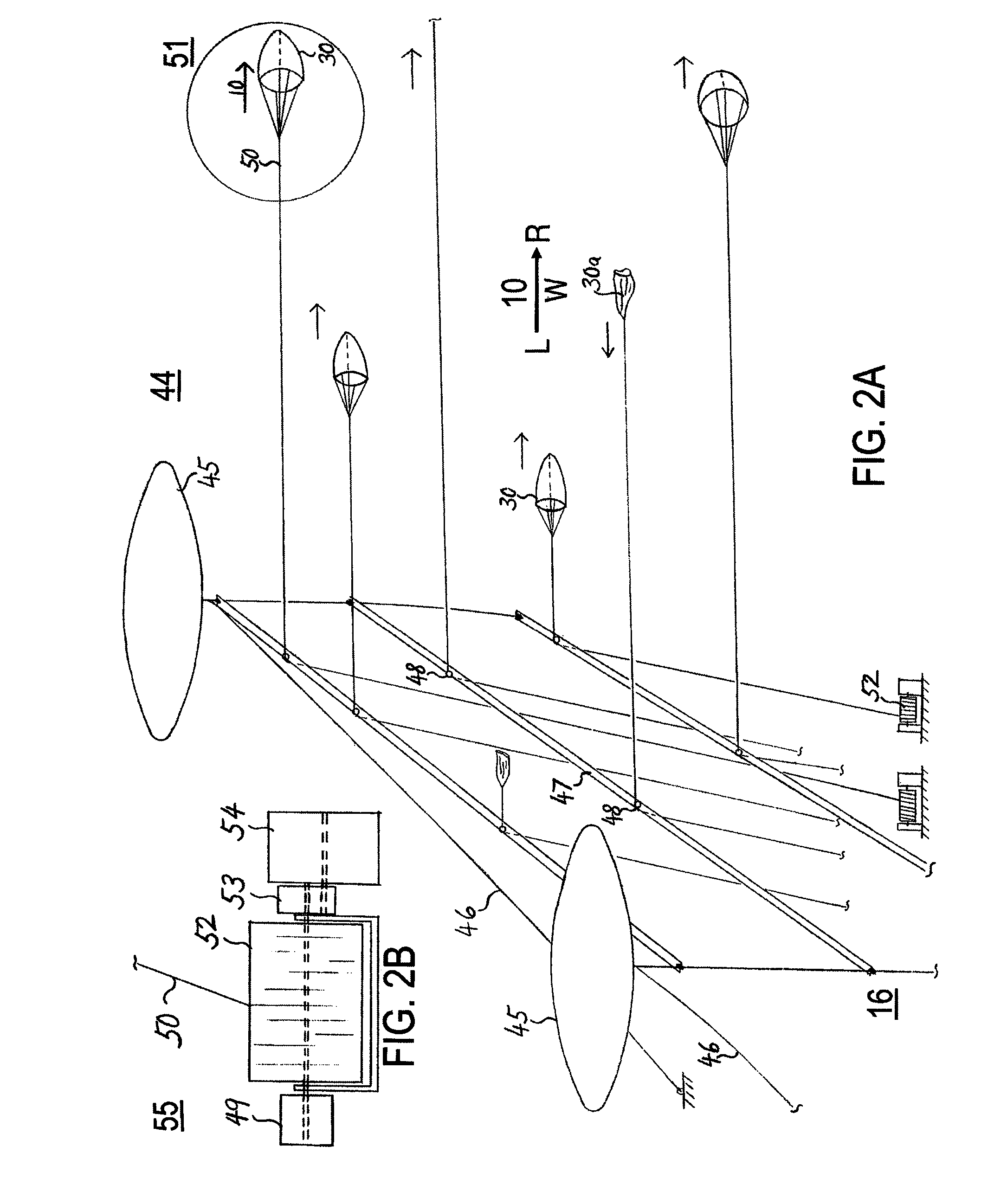
[0026]The structural configuration, concept and method of providing a plain air-bag, a windbag and / or a water-bag to trap and capture moving air current (wind) and / or water current, get carried along as it is swept away by the fluid's movement; for the generation of electricity; is herein disclosed. Using a windsock-shaped bag with a gaping “mouth” and enclosed rear-end to entrap, to capture moving wind / or water current; extracting, transforming its kinetic energy into mechanical and then electrical energy by means of a tether. In free “flight” / or flow; the windbag and / or water-bag may travel a longer distance horizontally; than rise in height / or sink in depth vertically. Due to lack of generation of aerodynamic lift, bags are incapable of actual aerial flight; in the real sense of the word “flying” as kites and planes are capable of. A windbag is only capable of actual aerial flight when integrated with airborne flying apparatus comprising: balloons / or shaped-inflatable bodies fill...


PUM


Abstract

A method of using a bagged power generation system comprising windbags and water-bags for harnessing wind and water power to produce electricity to meet the escalating energy needs of mankind. Windbags integrated with aerodynamically shaped inflatable bodies filled with lighter-than-air gas: HAV, UAV, airplanes; enabling the apparatus to attain high altitude to capture and entrap high velocity wind. Water-bags integrated with hydrodynamic shaped bodies HUV, UUV, Submarine-boats; enabling the apparatus to dive, capture and entrap swift moving tidal-currents. Attached tether-lines pulling on the rotating reel-drums and generators to produce electricity. Active control surfaces, turbo-fans, propellers provide precision control of the apparatus. A system configured to maximize fluids capture, retention and optimized extraction of its kinetic energy. An extremely scalable and environmentally friendly method, system, apparatus, equipment and techniques configured to produce renewable green energy with high productivity and efficiency.

Description

FIELD OF THE INVENTIONS[0001]This application claims the benefit of priority of SG application no. 201302987-1 filed Apr. 19, 2013, and SG application no. 201203067-2 filed Apr. 26, 2012, the contents of which are incorporated herein by reference for all purposes.[0002]The present invention relates to the harnessing of renewable “green” energy from the mass movement of naturally occurring fluid elements comprising wind and / or water; the capture and transformation of this kinetic energy into useful mechanical energy by means of a specialized bagged power generation system configured for producing electricity comprising of: (i) wind powered generators; (ii) water powered generators. In particular wind energy comprising: high altitude wind energy; the Jet Stream; and water energy comprising: marine currents; ocean gyres; Kuroshio; the Gulf Stream. The capture, entrapment, partial encapsulation and transformation of the fluid's kinetic energy into useful mechanical energy by means of te...

Claims


Application Information

Patent Timeline
Patent Type & Authority Patents(United States)
IPC IPC(8): F03D9/00H02P9/04F03B17/06F03D5/00
CPCF03D9/002F03D5/00F03B17/06Y02E10/28Y02E10/70Y02E10/725Y02E10/728F03D9/30F03D15/10H02K7/1853F03D9/25F03D9/008F05B2220/70F05B2240/922F05B2240/923F05B2270/18F05B2270/20Y02E10/74Y02E10/72Y02E10/30F05B2240/9176B64U10/60B64U2101/10B64U50/12B64U20/60B64U10/50Y02E10/20B64U2101/00F03D5/02H02K7/06B64C39/022B64C39/024F03D7/06
Inventor SIA, YIK HEI
Owner SIA YIK HEI
Why Eureka
Try Eureka