Floor covering, floor element and method for manufacturing floor elements

a technology of floor elements and floor coverings, applied in the field of floor coverings, can solve the problems of limited locking strength, relatively high risk of coupling coming loose, and male coupling parts made in v-shape, and achieve the effect of better and/or sturdier and/or simpler manufacturing of couplings

Active Publication Date: 2015-03-31
FLOORING IND LTD
View PDF331 Cites 81 Cited by
  • Summary
  • Abstract
  • Description
  • Claims
  • Application Information

AI Technical Summary

Benefits of technology

[0006]In general, the present invention, according to all of its aspects, aims at a floor covering or floor elements having, allowing, respectively, a better and / or sturdier and / or simpler to manufacture coupling among adjacent floor elements in a floor covering.

Problems solved by technology

A floor covering composed of floor elements with such coupling parts and locking portions, however, shows a limited strength of the locking, in particular of the locking in vertical direction, and has a relatively high risk of the coupling coming loose, even with a normal use of the floor covering.
The embodiment of WO 01 / 98604, for example, shows the disadvantage that the male coupling part is made in a V-shape, such that the bendable lip-shaped portion is supported in a relatively weak manner and the locking shows a limited strength.
Under the influence of a vertical pressure load onto the connection, for example, when walking thereon, a V-shaped coupling part may deform and a height difference may develop between two adjacent floor panels; under the influence of a horizontal tension load, for example, when the floor elements crimp in dry periods, a V-shaped male coupling part also may deform and there is an increased risk that a gap forms between two adjacent floor panels.
Moreover, due to the translation movement forces may occur having a splitting effect onto the substrate of the floor element, whereby in such floor element, in particular when coupling it repeatedly, the strength of the coupling may be lost.

Method used


Image

  • Floor covering, floor element and method for manufacturing floor elements
  • Floor covering, floor element and method for manufacturing floor elements
  • Floor covering, floor element and method for manufacturing floor elements

Examples


Embodiment Construction

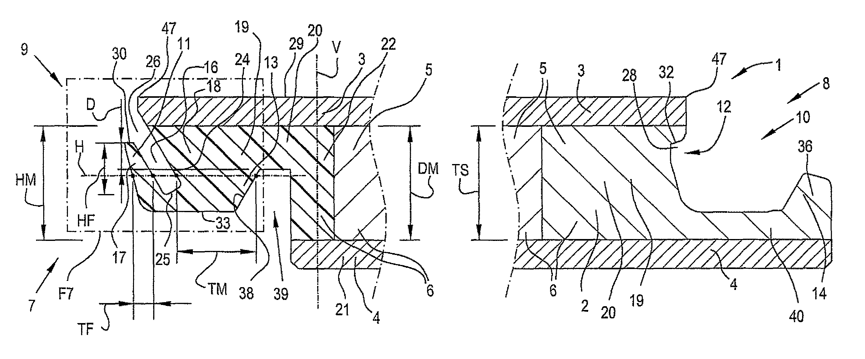
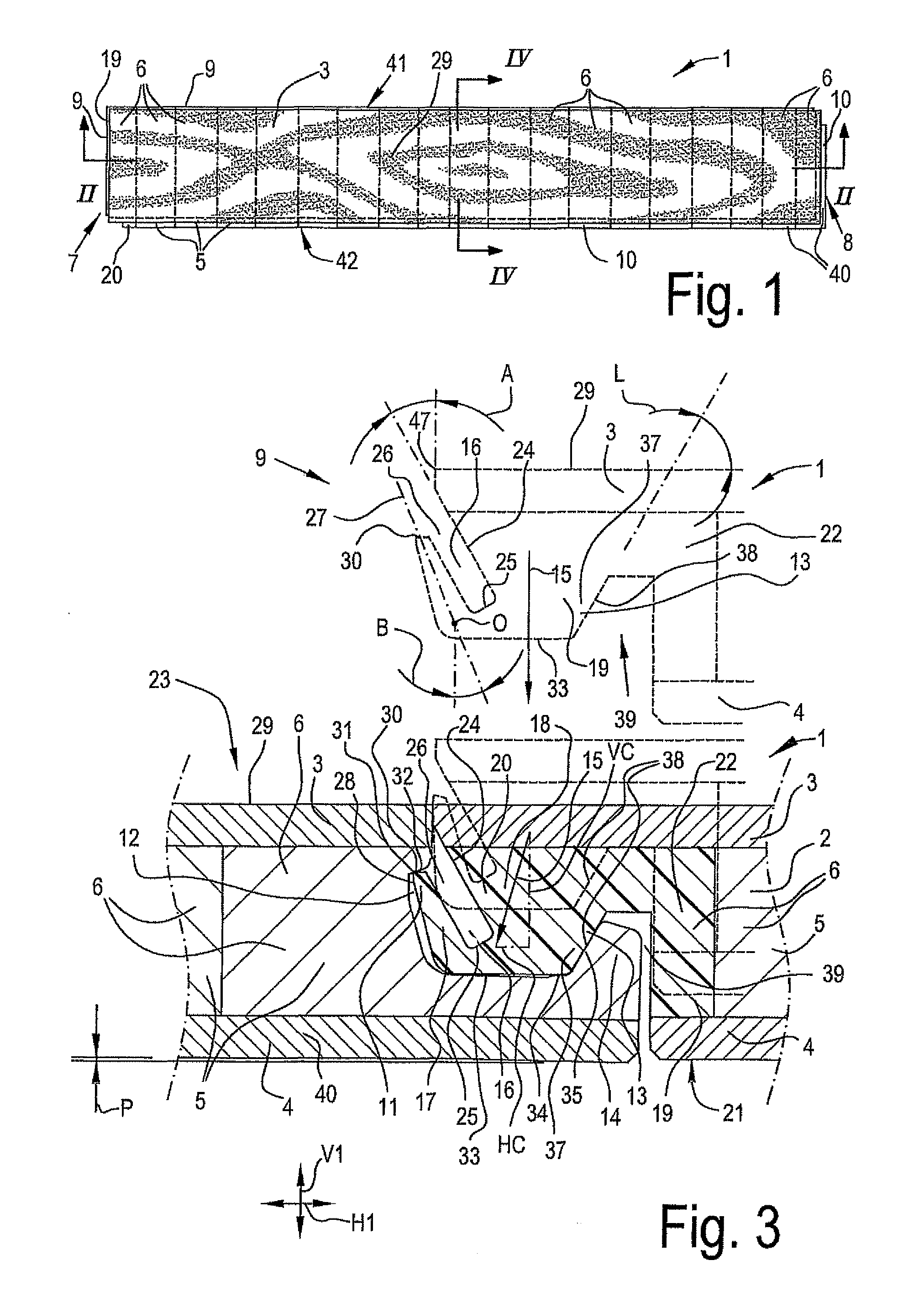
[0107]FIG. 1 represents a floor element 1 for forming a floor covering according to the invention. In this case, this relates to a rectangular and oblong floor element 1 that can be applied for composing a floor covering with, amongst others, the characteristics of the first, second, third and fourth aspects of the present invention.

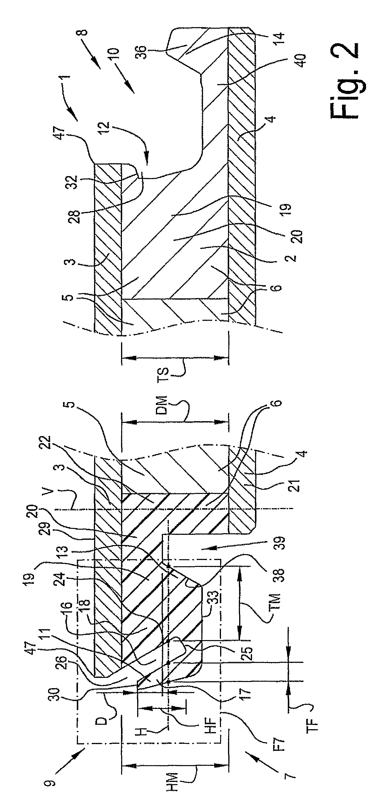
[0108]As is illustrated by means of FIG. 2, the floor element 1 comprises a substrate 2, a top layer 3 and, in this case, also a backing layer 4. According to the invention, the top layer 3 and the backing layer 4 may consist of any material. So, for example, may the top layer 3 consist of wood, such as veneer or a layer of wood with a thickness from 1 to 15 millimeters, as it is the case here, and, in the case that a backing layer 4 is present, this backing layer 4 may also consist of wood. The represented floor element 1 relates to a floor element of the type that is better known under the denomination “prefabricated parquet” or “engineered wood”. Such...


PUM

PropertyMeasurementUnit
thicknessaaaaaaaaaa
thicknessaaaaaaaaaa
angleaaaaaaaaaa

Abstract

Floor covering, made of floor elements, which, at least at two opposite sides, comprise a male and a female coupling part, which allow that two of such floor elements can be interconnected at the respective sides at the respective sides by pushing one of these floor elements with the associated male coupling part, by means of a downward movement, home into the female coupling part of the other floor element, wherein at least one of said coupling parts, either the male coupling part or the female coupling part, is made as least partially in a filled synthetic material composite, such as extruded wood.

Description

BACKGROUND OF THE INVENTION[0001]1. Field of the Invention[0002]This invention relates to a floor covering, to a floor element with which such floor covering can be composed, as well as to a method for manufacturing floor elements.[0003]2. Related Art[0004]Amongst others, the invention relates to floor elements comprising a substrate and a top layer, or to floor coverings composed of such floor elements. Herein, this may relate to the type of floor elements known from the DE 203 10 959 U1, the substrate of which is composed of laths, which substantially consist of softwood and wherein the top layer thereof consists of wood, such as floor elements with a top layer of veneer or with a wooden top layer with a thickness between 1 and 15 millimeters. However, the invention is not restricted to the abovementioned type of floor elements, but on the contrary also may relate to laminate floor panels having a top layer based on synthetic material, or to still other types of floor elements, fo...

Claims


Application Information

Patent Timeline
Patent Type & Authority Patents(United States)
IPC IPC(8): E04B1/00E04F15/02E04F15/04
CPCE04F15/02038E04F15/02E04F15/02033E04F15/048E04F2201/0138E04F2201/0153E04F2201/041E04F2201/049E04F2201/0529Y10T29/49629Y10T29/49623E04F15/102E04F2201/0146E04F2201/023E04F15/107E04F2201/0161E04F2201/0115E04F15/045E04F2201/013E04F2201/026E04F2201/043
Inventor CAPPELLE, MARK
Owner FLOORING IND LTD
Why Eureka
Try Eureka