Locking device for an adjustable steering column

a locking device and steering column technology, applied in steering parts, vehicle components, transportation and packaging, etc., can solve problems such as potential vibration and noise reduction, and achieve the effect of avoiding vibration and rattling noise in the open position of the manual operating lever, simple and cost-effective production, and comfortable and smooth limitation function

Active Publication Date: 2015-03-31
THYSSENKRUPP PRESTA AG
View PDF74 Cites 13 Cited by
  • Summary
  • Abstract
  • Description
  • Claims
  • Application Information

AI Technical Summary

Benefits of technology

[0007]Stated differently, it is thus one fundamental concept of the invention to interpose at least in the abutment position a damping body between the cam carrier and at least one stop of the countercam carrier. This damping body prevents an abrupt hard impact of the cam carrier on the stop and thus provides an acceptable and smooth abutment perception to the motor vehicle driver, when he actuates the securement device and turns the cam carrier and the countercam carrier correspondingly far relative to one another about the rotational axis. The damping body, further, also damps noises and potential vibrations. If the intermediate position were to be absent, the cam carrier in the abutment position would impact on the stop without any damping. The damping body or the damping bodies are comprised of a softer material, thus of a different material, than the cam carrier and the stop. The material of the damping body is elastically deformable. On impact, the damping body is correspondingly compressed between the stop and the cam carrier.
[0010]In terms of simple and cost-effective production of securement devices according to the invention, preferred variants provide for the damping body to be initially a separately fabricated structural part that is subsequently secured on the cam carrier or on the countercam carrier. The damping bodies can be secured directly on the cam carrier, for example directly on its cam or counterstops, or on the stop of the countercam carrier. If several stops are provided, it is advantageous to assign a damping body each to a particular stop. As already indicated above, the damping body comprises advantageously at least one elastically deformable body. The damping body can also be comprised entirely of such an elastically deformable body. The elastically deformable body or damping body advantageously is an elastomer body, such as for example rubber or another elastomer. The damping body, for the sake of simplicity, can be comprised of a monomaterial and thus of a single material. At a corresponding compression stress in the abutment position the elastically deformable material of the damping body advantageously leads to an energy degradation and thus to a conversion of the forces or energy introduced into the system into heat, such that the desired damping effect is generated. The damping body advantageously has rubber-elastic properties.
[0011]As already indicated, it can be provided for the cam carrier to impact on several stops of the countercam carrier in the abutment position with the interposition of several damping bodies. Herein, it is again feasible that the cam carrier in the abutment position with the interposition of several damping bodies impacts with several cams on several stops of the countercam carrier. As already explained in the introduction, it is understood that it is also feasible that the cam carrier comprises abutment regions or counterstops, separate from the cams, to which the corresponding explanations can apply. In terms of simple production and assembly, if there are several damping bodies, it is preferably provided for the damping bodies to be part of a common contiguous structural damping body part which is initially fabricated as a separate structural part and subsequently secured on the cam carrier or on the countercam carrier. The common structural damping body part can subsequently be secured in a single operating step or as an entity as a prefabricated structural part on the cam carrier or the countercam carrier or on the cams or countercams. It is in principle conceivable for the damping bodies to come into operation or to be effective upon reaching the closed position and / or also upon reaching the open position of the securement device. However, preferred embodiments of the invention provide in this context for the securement device to be in the open position when the cam carrier during the turning of cam carrier and countercam carrier relative to one another about the rotational axis in the abutment position, with the interposition of the damping body, impacts on the stop. In these embodiments, the damping bodies consequently dampen the braking of the opening of the manual operating lever at the end of the rotation movement. Vibrations and rattling noises in the open position of the manual operating lever can thereby be avoided.
[0012]The cooperation of the cam carrier and the stop of the countercam carrier with the interposition of the damping body or bodies forms overall a soft and attenuated stop function. In order to provide additionally a definitive end of the turning out-of-position possibility between the cam carrier and the countercam carrier, preferred embodiments of the invention provide for the countercam carrier, in addition to the stop or the stops, to comprise at least one end stop on which the cam carrier impacts in an end abutment position which differs from the abutment position. This end stop advantageously cooperates with a counterend stop or several counterend stops on the cam carrier, whose hardness is greater than the hardness of the damping body. In the simplest case the counterend stop or stops are each formed by an areal segment on each cam of the cam carrier, which is in direct contact with an end stop in the end abutment position. Between the end stop or the end stops and the particular counterend stops no damping body is provided, such that a hard end abutment position is reached. It is advantageously provided for the cam carrier, starting from the abutment position, to be movable into the end abutment position by the turning about the rotational axis relative to the countercam carrier with advancing compression of the damping body. In this manner, the maximally feasible compression of the damping body can be dimensioned in particular in order to produce continuous service capability and preferably a comfortable and smooth limitation function. The abutment faces of stop and end stop or stops as well as the end stops and counterend stops can extend parallel to the rotational axis. However, it is also feasible to provide an acute angle between rotational axis and these abutment faces. This acute angle is advantageously between 2° and 10°, preferably between 5° and 8°. Viewed toward the rotational axis, the angles of the abutment faces of stop and end stop are preferably different with respect to one another.

Problems solved by technology

The damping body, further, also damps noises and potential vibrations.

Method used


Image

  • Locking device for an adjustable steering column
  • Locking device for an adjustable steering column
  • Locking device for an adjustable steering column

Examples


Embodiment Construction

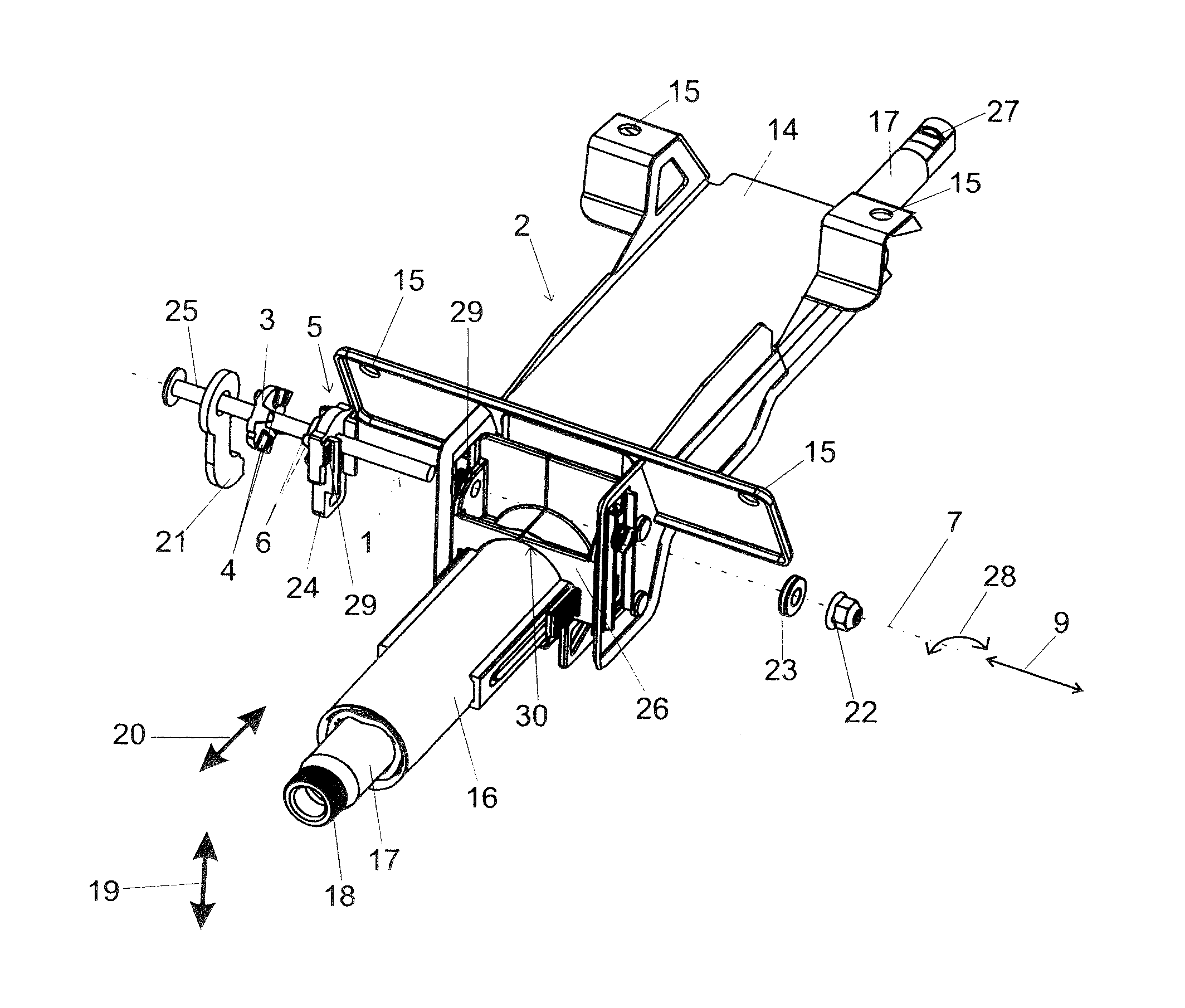
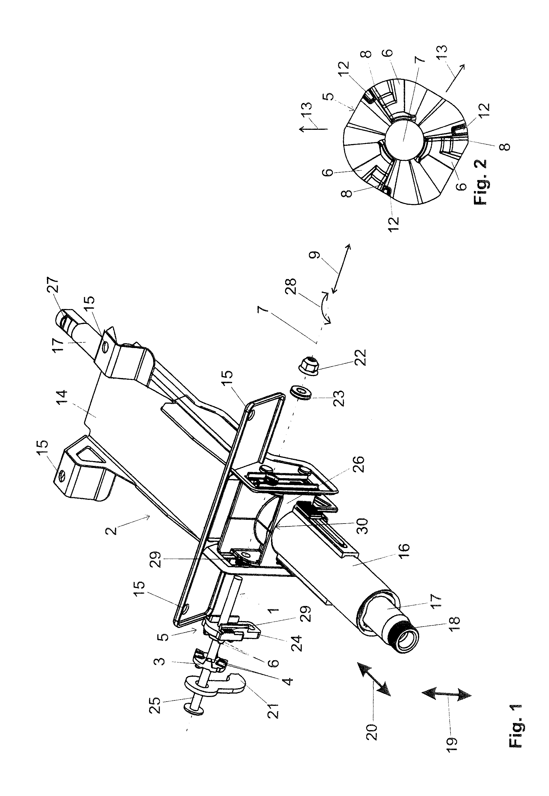
[0026]In FIG. 1 is depicted an adjustable steering column 2 implemented according to the invention, wherein, first, the features known per se in prior art of this steering column will be briefly described without implying that in the steering columns 2 according to the invention these features known per se in prior art need to be realized.

[0027]In the embodiment example depicted in FIG. 1, the adjustable steering column 2 comprises a bracket unit 14 which is secured by means of securement plates 15 on the body of a motor vehicle. On the bracket unit 14, optionally via a corresponding intermediate lever 26 known per se, a steering spindle bearing unit 16 is displaceably supported. To enable displacement, the securement device 1 must first be brought into its open position. In this open position of the securement device 1, the steering spindle bearing unit 16 together with the steering spindle 17 can be displaced in the length and / or height direction. In the depicted embodiment exampl...


PUM


Abstract

The invention relates to a locking device for an adjustable steering column for a motor vehicle, wherein the locking device has a cam bracket having at least one cam arranged in a fixed manner thereon and at least one mating cam bracket having at least one mating cam arranged in a fixed manner thereon and at least one stop. The cam bracket and the mating cam bracket are arranged so as to be rotatable relative to each other around an axis of rotation, and the cam of the first cam bracket interacts with the mating cam of the mating cam bracket upon rotation of the cam bracket and mating cam bracket relative to each other around the axis of rotation in order to generate a stroke in the longitudinal direction of the axis of rotation. The locking device has at least one dampening body which has at least one elastically deformable material that is softer than the cam bracket and the stop, wherein the cam bracket, upon rotation of the cam bracket and the mating cam bracket relative to each other around the axis of rotation, contacts the stop in a stop position in such a way that the dampening body is positioned therebetween.

Description

BACKGROUND OF THE INVENTION[0001]The present invention relates to a securement device for an adjustable steering column for a motor vehicle. The securement device comprises a cam carrier with at least one cam fixedly disposed thereon and at least one countercam carrier with at least one countercam fixedly disposed thereon and with at least one stop. The cam carrier and the countercam carrier are disposed such that they are turnable relative to one another about a rotational axis, and the cam of the first cam carrier, during the turning of the cam carrier and the countercam carrier relative to one another about the rotational axis, cooperates with the countercam of the countercam carrier for generating a deflection in the longitudinal direction of the rotational axis.[0002]Generic securement devices or clamping devices for adjustable steering columns are utilized in motor vehicles in order to be able to adapt the position of the steering wheel to the particular motor vehicle driver i...

Claims


Application Information

Patent Timeline
Patent Type & Authority Patents(United States)
IPC IPC(8): B62D1/184
CPCB62D1/184
Inventor HAHN, MICHAELFLEISCHER, MARTIN
Owner THYSSENKRUPP PRESTA AG
Why Eureka
Try Eureka