
Supply noise rejection in implantable medical devices

a medical device and implantable technology, applied in the field of implantable medical devices, can solve problems such as lack of an enclosure for an energy source, and achieve the effect of limiting or eliminating artifacts (noise signals)

Active Publication Date: 2015-04-07
MEDTRONIC INC
View PDF34 Cites 10 Cited by
  • Summary
  • Abstract
  • Description
  • Claims
  • Application Information

AI Technical Summary

Benefits of technology

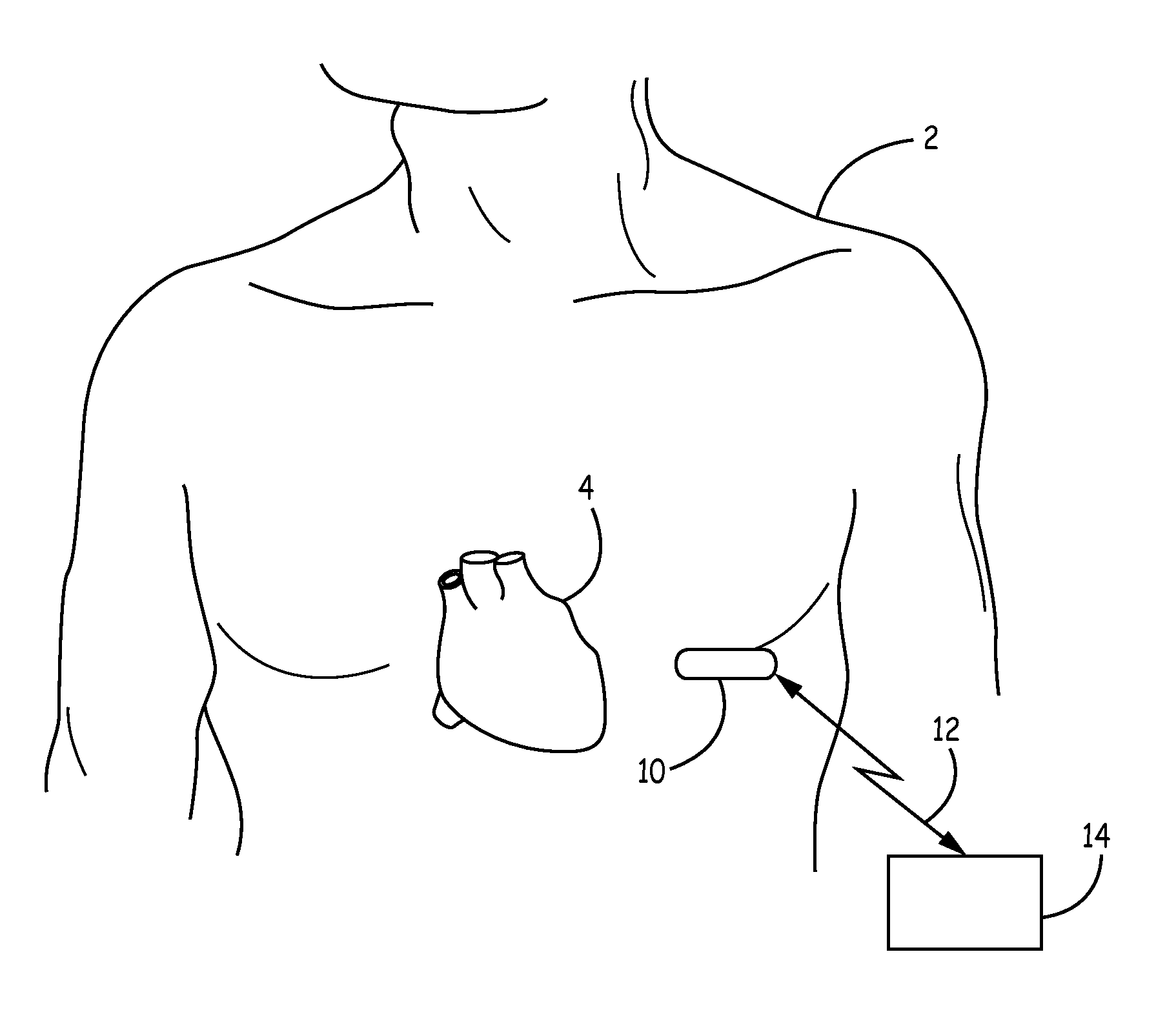
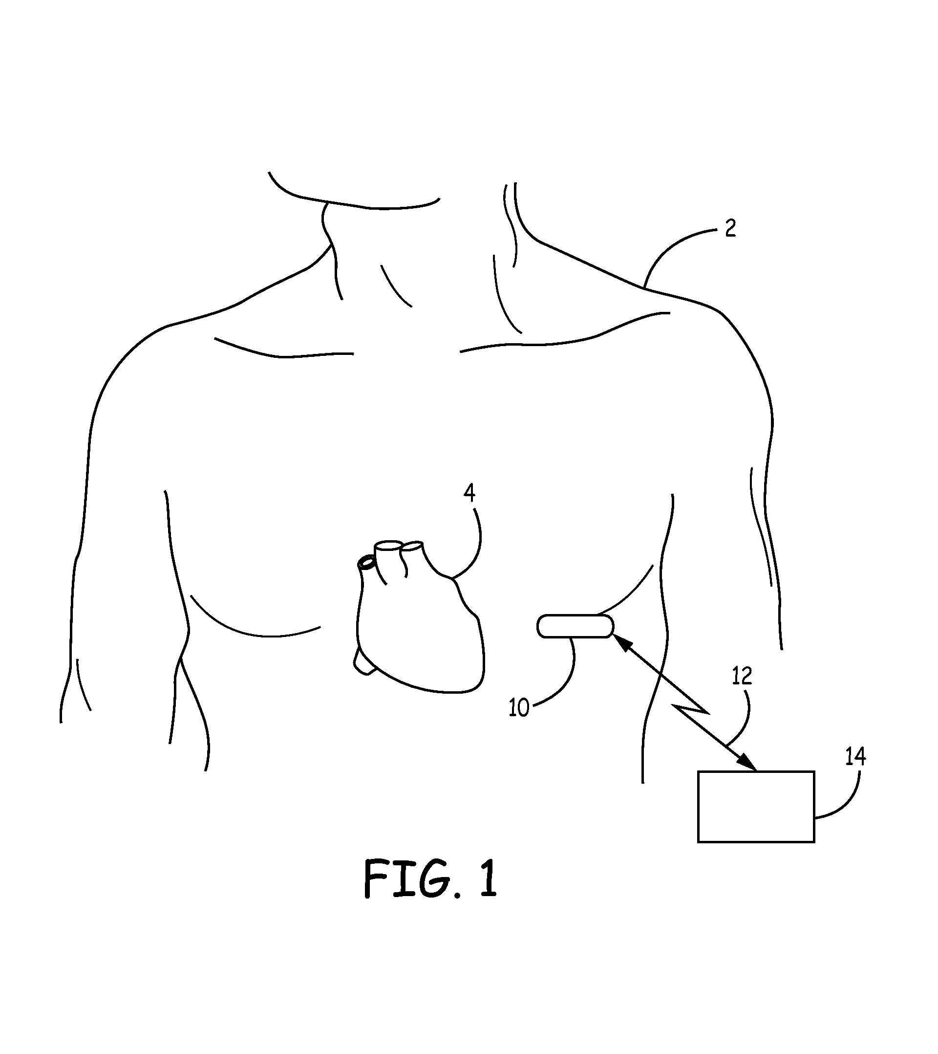
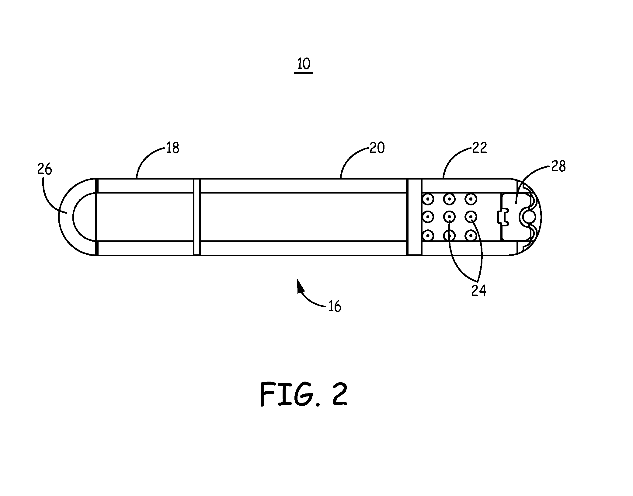
[0015]Still further, an implantable medical device is disclosed that is implantable in a biological tissue. The device includes a battery with an anode, a cathode, and a battery case that encloses the anode and the cathode. The battery case has an inner surface and an outer surface, and the anode and the cathode are disposed within a cavity defined by the inner surface and are electrically isolated from the battery case. The battery also includes a first electrode that is electrically connected to the outer surface of the battery case. The outer surface of the battery case is exposed to the biological tissue. The electrical isolation of the battery case from the active battery components is configured to limit or eliminate artifacts (noise signals) on a signal sensed by the first electrode.

Problems solved by technology

Among the challenges in the prior art is the lack of an enclosure for an energy source that is designed for use with sensing and or pacing electrodes.

Method used


Image

  • Supply noise rejection in implantable medical devices
  • Supply noise rejection in implantable medical devices
  • Supply noise rejection in implantable medical devices

Examples


Embodiment Construction

[0024]The invention and the various features and advantageous details thereof are explained more fully with reference to the non-limiting embodiments that are illustrated in the accompanying drawings and detailed in the following description. Descriptions of well-known components and processing techniques are omitted so as not to unnecessarily obscure the invention in detail but such descriptions are, nonetheless, included in the disclosure by incorporation by reference of the citations discussed. It should be understood, however, that the detailed description and the specific examples, while indicating preferred embodiments of the invention, are given by way of illustration only and not by way of limitation. Various substitutions, modifications, additions and / or rearrangements within the spirit and / or scope of the underlying inventive concept will become apparent to those skilled in the art from this detailed description.

[0025]The present disclosure facilitates the use of a battery...


PUM

PropertyMeasurementUnit
conductiveaaaaaaaaaa
electrically insulativeaaaaaaaaaa
electricallyaaaaaaaaaa

Abstract

The present invention provides an implantable medical device having at least two electrodes coupled to the device housing. The electrodes may be configured for sensing physiological signals such as cardiac signals and alternatively for providing an electrical stimulation therapy such as a pacing or defibrillation therapy. In accordance with aspects of the disclosure, the device housing provides a hermetic enclosure that includes a first housing section that is hermetically coupled to a second housing section. At least one of the at least two electrodes is coupled to an exterior surface of the first housing section that encloses the battery components of the device. The first housing section is electrically insulated from the cathode and anode of the battery.

Description

CROSS-REFERENCE TO RELATED APPLICATION[0001]This application claims the benefit of priority from U.S. Provisional Application No. 61 / 876,454, filed Sep. 11, 2013, which is incorporated herein by reference in its entirety.FIELD[0002]The disclosure relates generally to implantable medical devices of the type comprising integrated circuitry for performing monitoring of a physiologic state and / or therapy delivery. In particular, the disclosure pertains to an implantable device having an exposed energy source case.BACKGROUND[0003]Implantable medical devices are used to monitor and treat a variety of conditions. Examples of implantable medical devices are implantable loop recorders, implantable pacemakers and implantable cardioverter-defibrillators (ICDs), which are electronic medical devices that monitor the electrical activity of the heart and / or provide electrical stimulation to one or more of the heart chambers, when necessary. For example, cardiac signals may be monitored by an impla...

Claims


Application Information

Patent Timeline
Patent Type & Authority Patents(United States)
IPC IPC(8): A61N1/00A61N1/378
CPCA61N1/3787A61N1/3756A61N1/3758A61N1/378A61N1/3704A61B2560/04A61B2562/225A61N1/3968Y10T29/49172A61B5/24A61B5/287
Inventor REINKE, JAMES D.GORDON, CHARLES R.KUEHN, KEVIN P.TERRY, MICHAEL B.
Owner MEDTRONIC INC
Learn More