Method and rolling die for producing a screw with a variable thread pitch

a technology of screw and thread pitch, which is applied in the direction of bolts, applications, fastening means, etc., can solve the problems of limiting throughput and large material loss, and achieve the effect of fast and economical implementation

Active Publication Date: 2015-04-28
LUDWIG HETTICH
View PDF5 Cites 4 Cited by
  • Summary
  • Abstract
  • Description
  • Claims
  • Application Information

AI Technical Summary

Benefits of technology

[0004]It is the object of the invention to provide a method for manufacturing a screw with a continuous thread with a variable thread pitch, which method can be implemented quickly and economically, and to state means for implementing this method.
[0009]The inventor has found that, with the use of a rolling die designed in this manner, a screw with a variable thread pitch can in practical application be formed in an uncomplicated manner and—surprisingly to the inventor—with little rolling pressure. As a result of the above-defined geometry of the depressions according to the first exemplary embodiment, apart from rolling material into the depressions for forming the thread, there is practically no material transfer in the axial direction of the blank, and consequently the rolling forces can be kept astonishingly low.
[0010]The uncomplicated behaviour during rolling with this geometry of the rolling die is surprising to the average person skilled in the art. For example, the inventor knows of attempts for forming two separate threads with a different, but in each case constant, thread pitch on one blank in the same rolling process by means of a two-piece rolling die. In practice, this has proven difficult because the blank has a tendency to tilt across the direction of rolling. It is a surprising result of the rolling method according to the first embodiment that no such tilting occurs during rolling, but that variable threads of excellent quality can be rolled in a simple and uncomplicated manner instead.
[0012]According to the second embodiment this can be achieved in that the slope of the centre lines of the depressions at a first end of the rolling die where the rolling process of the blank commences, is varied relative to the slope at the—when viewed in the direction of rolling—opposite section of a second end of the rolling die, at which end the rolling process is completed. For, if the slopes of the depressions, or in other words the space between the depressions in a region of the first end, is increased when compared to the—when viewed in the direction of rolling—opposite region of the second end, during rolling this results in contraction of the corresponding section of the blank so that material is transported into the corresponding axial region of the finished screw. The opposite effect occurs if the slope or the pitch between adjacent depressions in the region of the first end of the rolling die is reduced relative to the slope in the corresponding region at the second end. During rolling this results in material transport of a volume of material out of the corresponding axial region.

Problems solved by technology

However, this approach is associated with disadvantage in that there is a relatively large loss of material during machining, and in that there is a comparatively extended duration of machining, which limits throughput.

Method used


Image

  • Method and rolling die for producing a screw with a variable thread pitch
  • Method and rolling die for producing a screw with a variable thread pitch
  • Method and rolling die for producing a screw with a variable thread pitch

Examples


first embodiment

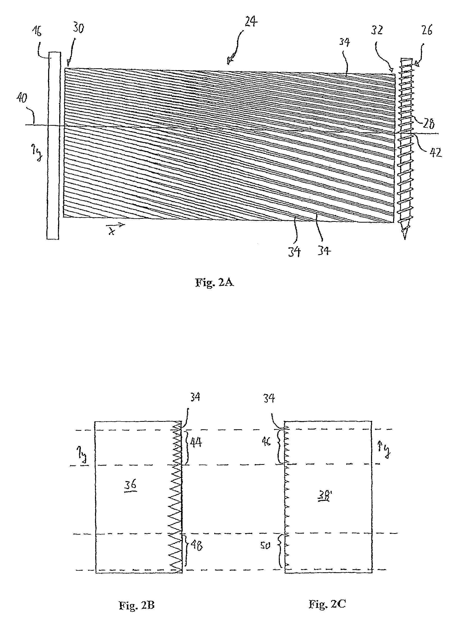
[0045]A second solution provides for varying the cross section of the thread ridge of the thread 28 by varying the flank angle and / or the thread depth in such a manner that in a region with a smaller thread slope or pitch the finish-rolled thread ridge comprises a smaller cross-sectional area, and in this way the volume defect is compensated for. The thread can thus have a more acute flank angle so that the thread, when viewed in longitudinal section of the screw, is narrower and comprises a more acute flank, and thus less material is used. In the method this can be implemented in a very simple manner by forming the widths of the depressions 34 at the second end of the rolling die 24 so as to be narrower and / or less deep in regions with a smaller thread pitch.

second embodiment

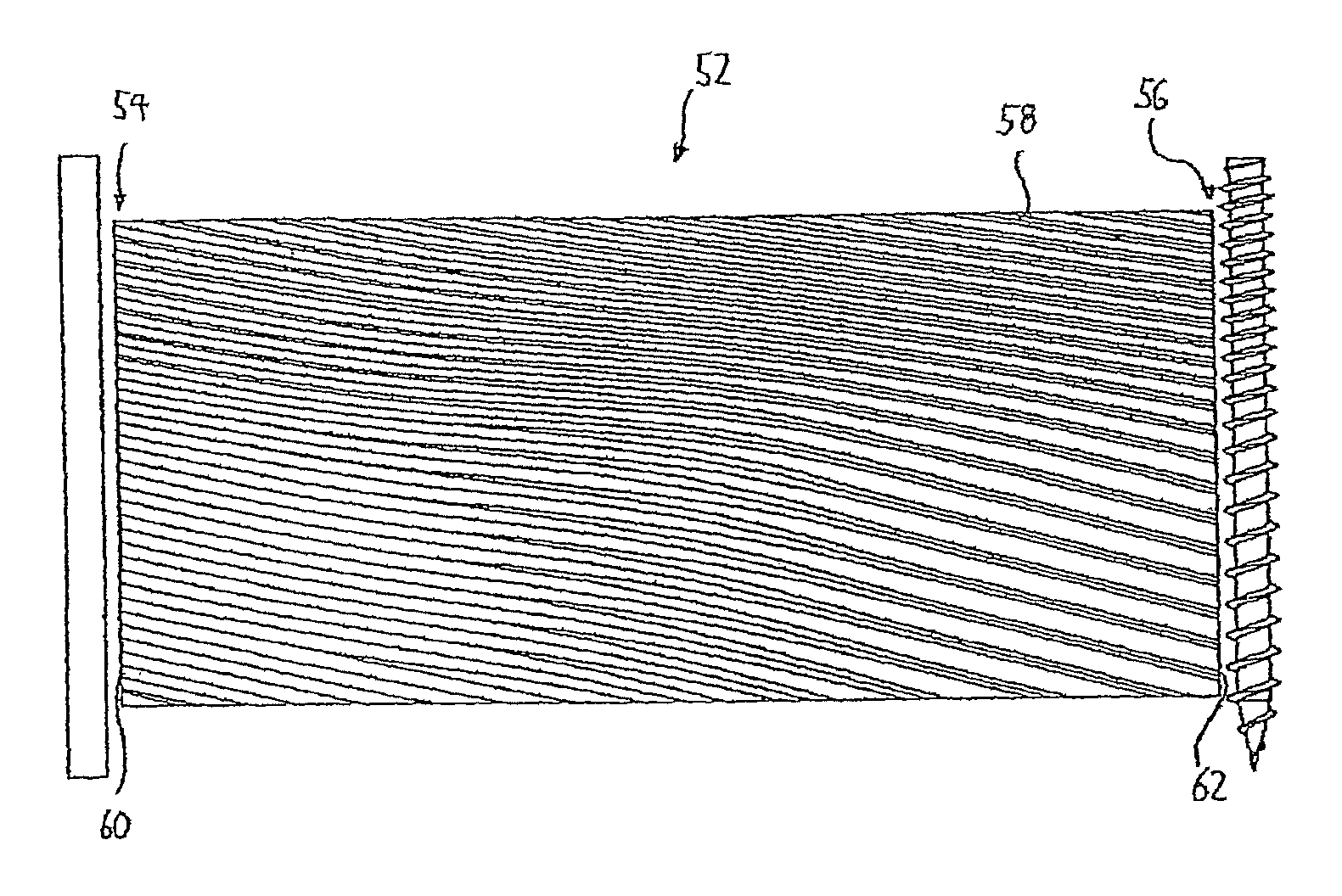
[0046]The third and preferred solution provides for the rolling profile to be designed in such a manner that a targeted volume transport from regions with a larger thread pitch into regions with a smaller thread pitch is caused, which volume transport just compensates for the volume defect. This third variant is described in the second embodiment, which hereinafter is described with reference to FIGS. 3A to 3C.

[0047]FIG. 3A shows a top view of a rolling die 52 according to a second embodiment of the present invention, which rolling die 52 comprises a first end 54 and a second end 56. In a manner similar to that shown in FIG. 2A, the rolling die 52 has a rolling profile comprising a multitude of elongated, curved, non-parallel depressions 58. The course of the depressions 58 is based on the one shown in FIG. 2A but has been additionally modified with a view to a special intended volume transport.

[0048]FIGS. 3B and 3C in turn show the top view of the end faces 60 or 62 of the first an...


PUM

PropertyMeasurementUnit
flank angle A1aaaaaaaaaa
flank angle A2aaaaaaaaaa
depth D1aaaaaaaaaa

Abstract

Disclosed herein is a method for manufacturing a screw comprising a continuous thread with a variable thread pitch, in which method a blank is rolled between two rolling dies, wherein in each rolling die a rolling profile is formed that comprises a host of curved non-parallel depressions. The depressions are designed and arranged in such a manner that during rolling no volume transport, or as little volume transport as possible, in the axial direction takes place, or a volume transport from a region of the blank where a thread section with a larger thread pitch is to be formed, to a region in which a thread section with a smaller thread pitch is to be formed takes place.

Description

BACKGROUND TO THE INVENTION[0001]The present invention relates to a method and a means for manufacturing a screw comprising a continuous thread with a variable thread pitch. In this document, the term “continuous thread” defines a single uninterrupted thread, in contrast to two separate threads on a screw.RELATED PRIOR ART[0002]A screw with a continuous thread with a variable thread pitch is, for example, described in WO 2009 / 015754. By means of a suitable variation in the thread pitch, residual stress can be generated in the bond between the screw and a component when the screw is driven into the component. According to the teaching of the above-mentioned patent specification, the variation in the thread pitch is to be selected such that the residual stress acts against a bond stress that occurs when the component is subjected to loads, so that at least the stress peaks of the resulting bond stress are reduced when the component is subjected to loads. Such a screw with a variable t...

Claims


Application Information

Patent Timeline
Patent Type & Authority Patents(United States)
IPC IPC(8): B21H3/02B21H3/06
CPCB21H3/06
Inventor HETTICH, ULRICH
Owner LUDWIG HETTICH
Why Eureka
Try Eureka