Speed reduction mechanism and motor torque transmission apparatus including the same

a technology of speed reduction mechanism and motor torque, which is applied in the direction of electric propulsion mounting, transportation and packaging, gearing, etc., can solve the problems of rotary shaft slanting, complex shape, and possible runout of rotary sha

Inactive Publication Date: 2015-05-19
JTEKT CORP
View PDF14 Cites 7 Cited by
  • Summary
  • Abstract
  • Description
  • Claims
  • Application Information

AI Technical Summary

Benefits of technology

[0018]The foregoing and further features and advantages of the invention will become apparent from the following description of example embodiments with reference to the accompanying drawings, wherein like numerals are used to represent like elements, and wherein:

Problems solved by technology

In the motor torque transmission apparatus described in JP 2007-218407 A, a plurality of the outer pins needs to be prepared, and further, the outer peripheral portions of the revolving members need to be formed into a complex shape, which is uneconomical.
However, when the reduction-transmission mechanism including the external gears and the internal gear is used in motor torque transmission apparatus for an automobile, if a load caused by a centrifugal force is exerted on a differential mechanism-side end portion of the motor shaft (rotary shaft) from the external gears during output of the power, the rotary shaft may be slanted or runout of the rotary shaft may occur.
If the rotary shaft is slanted or runout of the rotary shaft occurs, the external gears are meshed with the internal gear while being slanted, and therefore, off-center between the internal gear (rotation force applying member) and the output target is caused, resulting in hindrance to smooth rotation of the differential case.

Method used


Image

  • Speed reduction mechanism and motor torque transmission apparatus including the same
  • Speed reduction mechanism and motor torque transmission apparatus including the same
  • Speed reduction mechanism and motor torque transmission apparatus including the same

Examples


Embodiment Construction

[0024]Hereinafter, a speed reduction mechanism and motor torque transmission apparatus including the speed reduction mechanism, according to an embodiment of the invention will be described in detail with reference to the accompanying drawings.

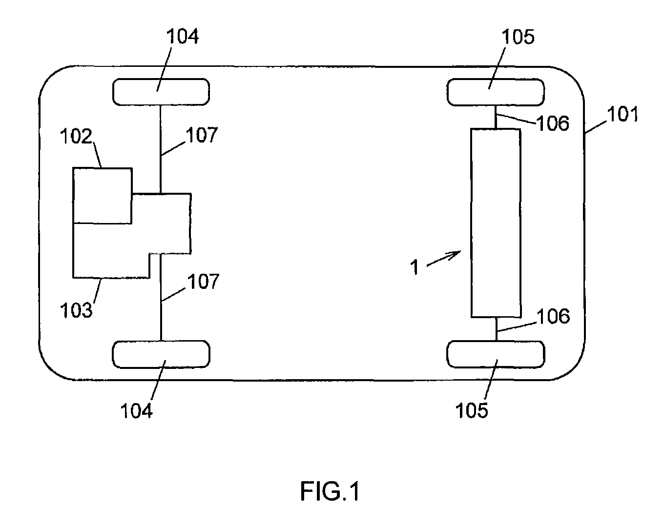
[0025]FIG. 1 schematically shows a four-wheel-drive vehicle 101. As shown in FIG. 1, the four-wheel-drive vehicle 101 includes a front wheel-side power system and a rear wheel-side power system. The front wheel-side power system has an engine as a drive source. The rear wheel-side power system has an electric motor as a drive source. The four-wheel-drive vehicle 101 includes motor torque transmission apparatus 1, an engine 102, a transaxle 103, a pair of front wheels 104 and a pair of rear wheels 105.

[0026]The motor torque transmission apparatus 1 is arranged in the rear wheel-side power system in the four-wheel-drive vehicle 101, and is supported on a vehicle body (not shown) of the four-wheel-drive vehicle 101.

[0027]The motor torque transmis...


PUM


Abstract

A speed reduction mechanism includes a bearing mechanism arranged on an axis of an output mechanism and including ball bearings that are arranged in parallel with each other in an axial direction of a differential case. The differential case is rotatably supported by the ball bearings of the bearing mechanism such that the entirety of an outer periphery of one of the ball bearings faces an inner periphery of a first housing element that accommodates the differential case and that is made of a material having a stiffness lower than a stiffness of a material of a rotation force applying member, and the entirety of an outer periphery of the other one of the ball bearings faces an inner periphery of the rotation force applying member.

Description

INCORPORATION BY REFERENCE[0001]The disclosure of Japanese Patent Application No. 2012-155818 filed on Jul. 11, 2012 including the specification, drawings and abstract is incorporated herein by reference in its entirety.BACKGROUND OF THE INVENTION[0002]1. Field of the Invention[0003]The invention relates to a speed reduction mechanism that is suitable for use in, for example, an electric vehicle including an electric motor as a drive source, and also relates to motor torque transmission apparatus including the speed reduction mechanism.[0004]2. Description of Related Art[0005]A conventional motor torque transmission apparatus includes an electric motor and a reduction-transmission mechanism. The electric motor generates motor torque. The reduction-transmission mechanism transmits driving force based on the motor torque of the electric motor, to a differential mechanism. The motor torque transmission apparatus is installed in, for example, an automobile (refer to, for example, Japane...

Claims


Application Information

Patent Timeline
Patent Type & Authority Patents(United States)
IPC IPC(8): F16H48/30F16H1/32B60K1/00B60K17/356
CPCF16H1/32B60K1/00B60K17/356F16H48/30B60K2001/001F16H2001/325B60K17/04F16H57/021F16H2057/02013
Inventor NOMURA, KEITASUZUKI, KUNIHIKOTAKUNO, HIROSHI
Owner JTEKT CORP
Why Eureka
Try Eureka