
Collaboration system and method

a collaboration system and system technology, applied in the field of collaboration systems, can solve the problems of inability to easily share desktop content, slow updates or momentary screen freezes, and performance may be greatly compromised, so as to reduce bandwidth usage, reduce encoding and decoding resources, and reduce the effect of bitra

Active Publication Date: 2015-05-19
MITEL
View PDF25 Cites 2 Cited by
  • Summary
  • Abstract
  • Description
  • Claims
  • Application Information

AI Technical Summary

Benefits of technology

[0035]whereby transmitting only said encoded content within said area minimizes encoding and de-coding resources and bandwidth resources.
[0036]Advantageously, any desktop content, such as video, may be shared easily among participants in real-time, without relying on screen capture techniques and additional hardware. The video content is encoded in real-time using compression techniques which lowers the bitrate for a reduction in bandwidth usage during transmission between the participants. In addition, this desktop sharing method requires less processing resources and bandwidth requirements than prior art methods. The combination of the network apparatus and the video application server solution avoids the need for costly multipoint control units (MCUs), reducing overall costs and additionally reducing MCU quality impacting encoding / de-coding and associated increased latency.

Problems solved by technology

One problem inherent in existing collaboration systems is the inability to easily share desktop content, such as multimedia content.
Other screen sharing solutions often require significant bandwidth to send a full video of the presenter's screen and can often result in slow updates or momentary screen freezes for the participant viewers, and the performance may be greatly compromised by slower network connections.
However, such systems employing MCUs require substantial encoding / decoding resources, bandwidth resources, and associated increased latency.

Method used


Image

  • Collaboration system and method
  • Collaboration system and method
  • Collaboration system and method

Examples


Embodiment Construction

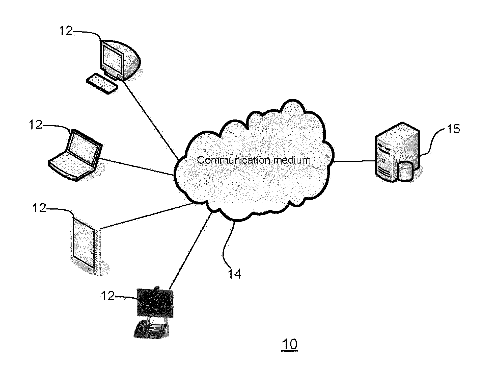
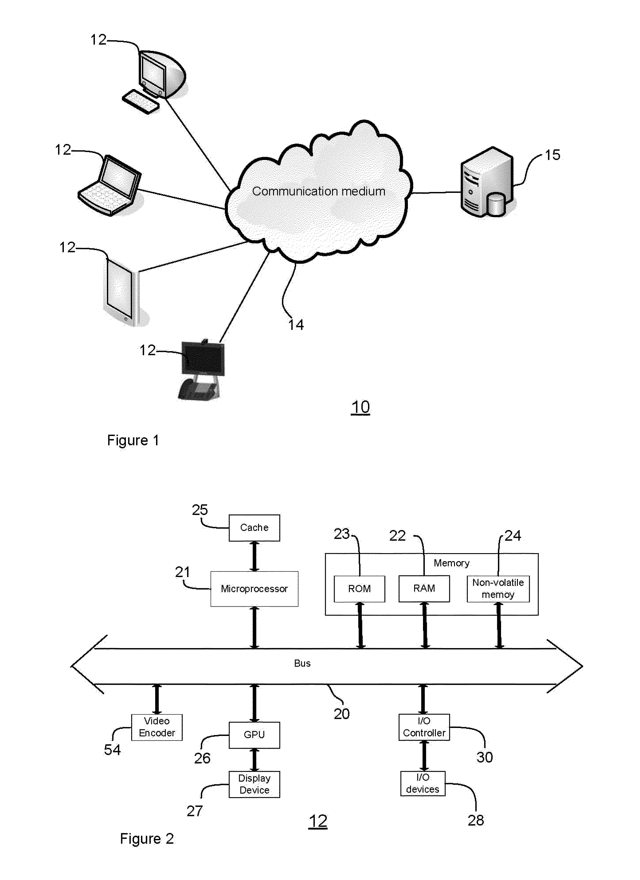
[0041]The detailed description of exemplary embodiments of the invention herein makes reference to the accompanying block diagrams and schematic diagrams, which show the exemplary embodiment by way of illustration and its best mode. While these exemplary embodiments are described in sufficient detail to enable those skilled in the art to practice the invention, it should be understood that other embodiments may be realized and that logical and mechanical changes may be made without departing from the spirit and scope of the invention. Thus, the detailed description herein is presented for purposes of illustration only and not of limitation. For example, the steps recited in any of the method or process descriptions may be executed in any order and are not limited to the order presented.

[0042]Moreover, it should be appreciated that the particular implementations shown and described herein are illustrative of the invention and its best mode and are not intended to otherwise limit the ...


PUM


Abstract

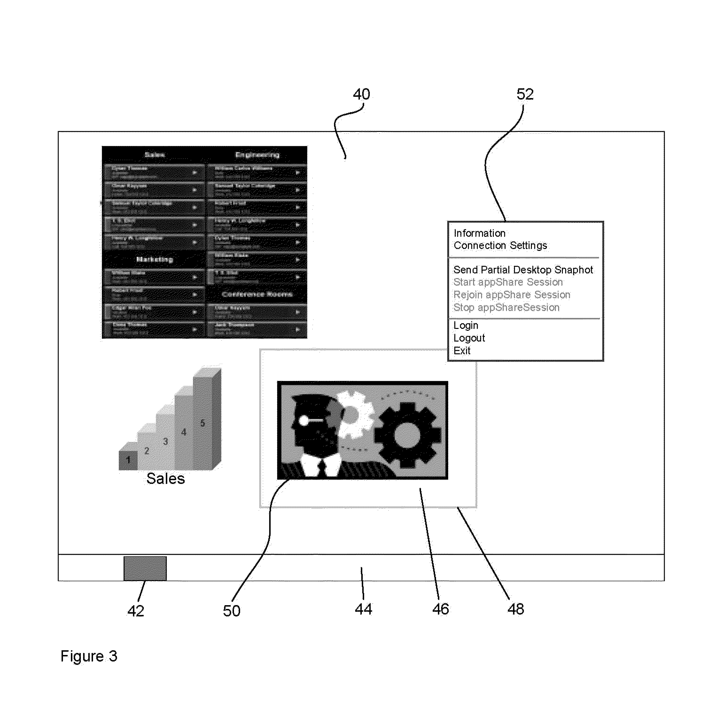
A network apparatus in a collaboration system with a plurality of participants, the apparatus comprising: a processing structure; and a memory including computer program code, wherein the memory and the computer program code are configured, with the processing structure, to cause the network apparatus to at least: present content on a display coupled to the processing structure; select a portion of the display for sharing, the portion having the shared content; simultaneously send said shared content to said display and to an encoder for encoding; automatically discover a network server configured to distribute the shared content with the plurality of participants; couple the apparatus to the network server and transmit the shared content to the network server for distribution to at least one of the plurality of participants, such that the shared content is encoded and decoded, and displayed in real-time.

Description

CROSS-REFERENCE TO RELATED APPLICATIONS[0001]This application claims the benefit of priority to U.S. Provisional Application Ser. No. 61 / 567,568, filed on Dec. 6, 2011.FIELD OF THE INVENTION[0002]The present invention relates to collaboration systems.BACKGROUND OF THE INVENTION[0003]Collaboration systems are well known. One problem inherent in existing collaboration systems is the inability to easily share desktop content, such as multimedia content. Generally, sharing content on a desktop, or a portion thereof, may be achieved in a number of ways. For example, one such method involves a screen capture procedure using multiple keys or commands, pasting the captured content onto a clipboard, saving the clipboard contents, launching a messaging client, such as an email application program, attaching the clipboard contents to a message, selecting a destination, and finally sending the message.[0004]Other screen sharing solutions often require significant bandwidth to send a full video ...

Claims


Application Information

Patent Timeline
Patent Type & Authority Patents(United States)
IPC IPC(8): H04N7/15H04L29/06
CPCH04N7/15H04L65/4038H04L65/4023H04L65/4025
Inventor SHEN, FRANCISFRANCISCO, PAULO
Owner MITEL
Learn More