Indentation tester

a technology of indentation tester and indentation depth, which is applied in the direction of instruments, measuring devices, and investigating material hardness, etc., can solve the problems of reducing resolution, small margin for baseline position, and inability to measure the maximum indentation depth to satisfaction, etc., and achieves the effect of convenient and cheap production

Active Publication Date: 2015-06-02
MITUTOYO CORP
View PDF17 Cites 6 Cited by
  • Summary
  • Abstract
  • Description
  • Claims
  • Application Information

AI Technical Summary

Benefits of technology

[0007]The present invention provides an indentation tester capable of readily and cheaply adjusting vertical-direction positioning drift due to individual differences of an indenter when indenters are switched.
[0013]The present invention enables adjustments to be readily made so as to position an indenter coupling at a vertical-direction baseline position of an indenter position detector when an indenter is positioned at a sample surface. In addition, the present invention enables adjustments to be readily and cheaply made to vertical-direction positioning drift that occurs when switching indenters due to individual differences in the indenter.

Problems solved by technology

However, due to the extremely high sensitivity of the device measuring the indentation depth, there is an exceptionally small margin for a baseline position.
Thus, when the indentation test is performed after switching indenters, there is a risk that measurement of a maximum indentation depth may not be performed to satisfaction or that resolution may be reduced.
The operation of switching indenters thus requires time and may also increase costs.

Method used


Image

  • Indentation tester
  • Indentation tester
  • Indentation tester

Examples


first embodiment

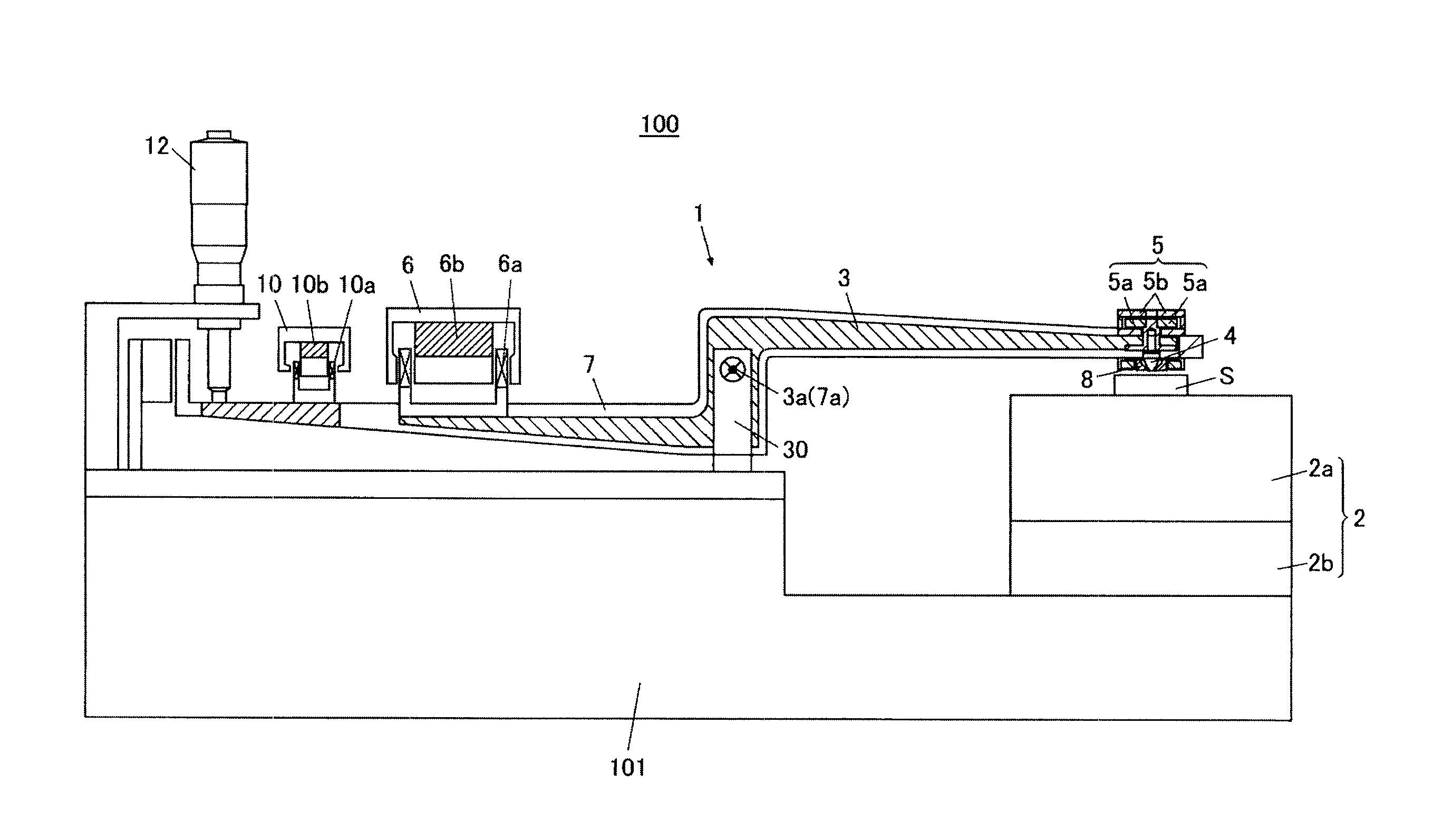
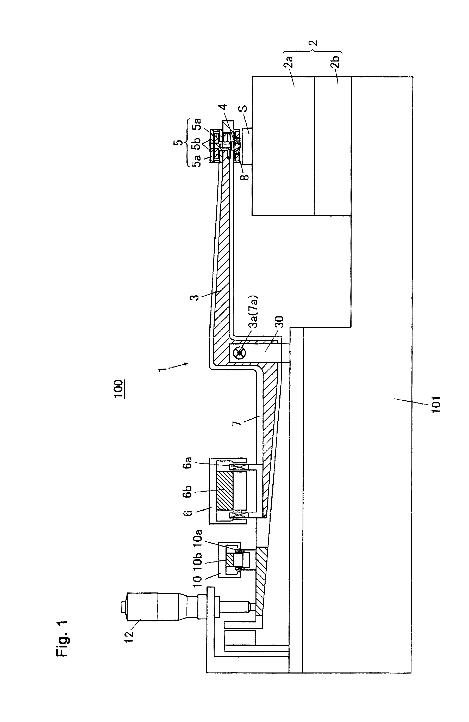
[0027]An indentation tester 100 according to a first embodiment is a lever-type instrumented indentation tester capable of continuously monitoring a test force (load) applied to an indenter 4 and an indentation depth of the indenter 4.

[0028]As shown in FIGS. 1 to 5, the indentation tester 100 includes a tester main body 1 applying the test force to a sample S; a controller 200 controlling various components of the tester main body 1; a display 300; and an operator 400.

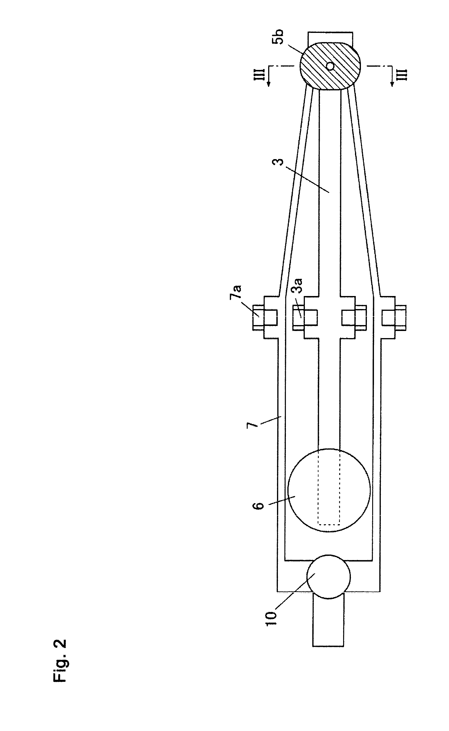
[0029]The tester main body 1 includes, for example: a stand 2 on which the sample S is placed; a load lever 3; an indenter column 41; a displacement sensor movable portion 5a (indenter coupling); a first force motor 6 (load-applying mechanism or load applier); a reference lever 7 (pressure brace); a contactor 8 (indenter reference); an adjustment mechanism (adjuster) 9; a displacement sensor fixed portion 5b (indenter position detector); a second force motor 10 (indenter reference driver); a stopper 12; and the control...

second embodiment

[0054]The second embodiment differs from the first embodiment in that the second embodiment applies the present invention to an indentation tester 110, which is a direct instrumented indentation tester, instead of to the indentation tester 100, which is a lever-type instrumented indentation tester. Specifically, the indentation tester 110 of the second embodiment is a direct instrumented indentation tester capable of continuously monitoring the test force (load) applied to the indenter 4 and the indentation depth for the indenter 4. Moreover, in order to simplify the description, configurations similar to those of the first embodiment are given the same reference numerals and a detailed description thereof is omitted.

[0055]As shown in FIGS. 6 and 7, the indentation tester 110 includes, for example: a sample stage 21 on which the sample S is placed; the indenter column 41; a displacement sensor movable portion 5a (indenter coupling); a first load transmitter 44; an indenter column gu...

example 1

Alternate Example 1

[0066]An example shown in FIG. 8 differs from the first embodiment in the shape of an indenter 4A, the shape of a contactor 8A, and an attachment position of an adjustment mechanism 9A, for example. Specifically, the indenter 4A has a platform 43A on which the adjustment mechanism 9A can be placed, the platform 43A being formed near an outer circumferential surface of a portion of the indenter 4A in contact with a bottom surface of an indenter column 41A. The indenter 4A thus enables the adjustment mechanism 9A to be placed and held on the platform 43A. In Alternate Example 1, a second hollow disk 91B is placed on the platform 43A of the indenter 4A and a top surface of a first hollow disk 91A is in contact with a bottom surface of the indenter column 41A. Specifically, Alternate Example 1 enables the adjustment mechanism 9A to be held by the indenter 4A rather than the contactor 8A.

[0067]As described above, the adjustment mechanism 9A is configured such that the ...


PUM

PropertyMeasurementUnit
forceaaaaaaaaaa
depthaaaaaaaaaa
heightaaaaaaaaaa

Abstract

Indentation tester capable of adjusting vertical-direction positioning drift due to individual differences of an indenter when indenters are switched includes an adjustment mechanism. The adjustment mechanism adjusts relative vertical-direction positions of a displacement sensor movable portion and a displacement sensor fixed portion. The adjustment mechanism includes a first hollow disk having a spiraling surface formed on a bottom surface; and a second hollow disk having a spiraling surface formed on a top surface. The spiraling surface of the second hollow disk has a thread equal to that of the spiraling surface of the first hollow disk. The first hollow disk rests on the second hollow disk such that the bottom surface of the first hollow disk is overlaid on the top surface of the second hollow disk. The first hollow disk and the second hollow disk are capable of rotation on a center axis of an indenter column.

Description

CROSS-REFERENCE TO RELATED APPLICATIONS[0001]The present application claims priority under 35 U.S.C. §119 of Japanese Application No. 2012-123893, filed on May 31, 2012, the disclosure of which is expressly incorporated by reference herein in its entirety.BACKGROUND OF THE INVENTION[0002]1. Field of the Invention[0003]The present invention relates to an indentation tester.[0004]2. Description of Related Art[0005]Conventionally, a material tester is known in which an indentation tester forms an indentation by pressing an indenter column into a surface of a sample, the indenter column having an indenter on a foremost end thereof. The indentation tester then measures a depth of the indentation (displacement amount of the indenter) with a displacement gauge. Using a relationship between the displacement amount and a load placed on the indenter, the indentation tester measures values for physical characteristics of the sample, such as hardness. (See, for example, Japanese Patent Laid-ope...

Claims


Application Information

Patent Timeline
Patent Type & Authority Patents(United States)
IPC IPC(8): G01N3/44G01N3/42
CPCG01N3/42G01N3/44G01N2203/021G01N2203/0206
Inventor FURUTA, EIJISAWA, TAKESHI
Owner MITUTOYO CORP
Why Eureka
Try Eureka