Means for controlling the progression of myopia

a technology of myopia and progression, applied in the field of multizone, non-multifocal contact lenses, can solve the problems of undesirable pathologies, too large focusing power of the eye, and blurred vision, and achieve the effects of reducing preventing the progression of myopia, and reducing the elongation of the ey

Active Publication Date: 2012-08-14
THE VISION CRC LTD
View PDF17 Cites 48 Cited by
  • Summary
  • Abstract
  • Description
  • Claims
  • Application Information

AI Technical Summary

Benefits of technology

[0011]The present invention provides a multi-zone contact lens for inhibiting the progression of myopia in an eye, a method of forming such a lens, and a method of inhibiting the progression of myopia in an eye by the use of such a lens. The lens basically has a central optical zone that approximates in size the normal pupil diameter of the eye and that has a refractive power selected or adapted to give the eye clear distance vision, and a peripheral optical zone that substantially falls outside the normal pupil diameter of the eye and that has a refractive power sufficient to focus oblique peripheral rays entering the patient's eye through the peripheral zone onto a focal plane located on or in front of the peripheral region of the retina. While such peripheral focus provides the stimulus for reducing elongation of the eye in accordance with the teachings of Smith, two-zone lenses of this type—especially where the peripheral zone is annular and surrounds the central zone—are much more readily and cheaply made than the lenses disclosed in the Smith patent and can potentially introduce less aberrations such as distortion to the peripheral image.
[0014]On the other hand, it is preferred that the maximum diameter of the central zone should not be more than 1 mm greater than the normal pupil diameter. Where an annular peripheral optical zone is employed, the inner diameter preferably approximates the outer diameter of the central zone and the outer diameter will normally be less than 8 mm. The total diameter of the contact lens will typically lie between 13-15 mm, the additional area being formed by a skirt-like ring or carrier portion that serves to assist in locating and retaining the lens in position on the eye.
[0015]As is common with contact lenses, the rear surface is shaped to conform to the shape of the cornea of the patient and the front surface is contoured to create—together with the shape of the rear surface—the desired optical zones with their respective refractive powers. However, with the contact lenses herein envisaged, the difference in refractive power between the central zone and the peripheral optical zone can be as great as 8 Diopters and the discontinuity in shape of the front lens surface at the junction of the central and peripheral zones can be significant. Accordingly, it may be desirable to shape the front of the lens at this junction to form a transition zone which smooths the transition between the shapes of the different zones and / or which provides progressive increase in refractive power in a narrow band between the zones. The purpose of the transition zone, however, is to both smooth the external surface of the lens and to reduce optical artifacts and distortions that may be introduced by a sudden change in refractive power over a short distance. Simply blending or filleting the curves is often sufficient even though it may provide a narrow ring with indeterminate refractive properties.
[0019]Still further, according to embodiments of the present invention, the present invention is directed to a contact lens for use in reducing the progression of myopia in an eye of a wearer comprising a transparent material having front and rear surfaces, wherein the rear surface provides a base-curve adapted to fit the eye; and wherein the front surface comprises; a central optical zone curved so that, together with the base-curve, said central optical zone produces a central optical zone refractive power adapted to provide the wearer with clear distance vision in a central region of the retina of the eye, the central optical zone being substantially circular in shape of at least 3 mm in diameter but not more than 1 mm less than the normal diameter of the pupil of the eye; and an annular peripheral optical zone surrounding said central zone and curved so that, together with the base-curve, said peripheral zone is adapted to produce a peripheral optical zone refractive power, when the lens is worn, that is greater than said central optical zone refractive power by an amount greater than 1 Diopter and sufficient to focus off-axis rays that enter the eye through said peripheral zone onto a focal plane that is substantially on, or anterior to, the retina in a peripheral region of the retina located around said central region.
[0020]Still further, embodiments of the present invention are directed to a method for forming a contact lens for reducing the progression of myopia in an eye of a wearer, comprising forming on a transparent material a rear surface comprising a base-curve that is adapted to fit an eye of a wearer of the lens; and forming on the transparent material, a front surface spaced from said rear surface. The front surface comprises a central optical zone, the dimensions of said central optical zone are selected so the minimum dimension of said central optical zone substantially approximates the normal diameter of the pupil of the eye and that is curved so that, together with the base-curve, said central optical zone generates a central zone refractive power that provides the wearer with clear distance vision in a central region of the retina of the eye, and a peripheral optical zone that surrounds said central optical zone and lies substantially outside the normal diameter of the pupil of the eye, said peripheral optical zone is curved so that, together with the base-curve, said peripheral optical zone generates a peripheral optical zone refractive power that is greater than said central optical zone refractive power by an amount sufficient to focus peripheral rays entering the eye through the peripheral optical zone onto a focal plane that lies on or anterior to a peripheral region of the retina of the eye, when the lens is worn on the eye.

Problems solved by technology

Myopia or short-sightedness is a problem of the eye wherein objects at a distance are focused in front of the retina, causing blurred vision; that is, the focusing power of the eye is too great.
A number of undesirable pathologies are associated with progressive myopia.
It is assumed that, with emmetropia, this mechanism works well but that, in myopia, the elongation is excessive while, in hyperopia, it is insufficient to allow good focus of the axial rays.
However, the lenses, especially contact lenses, suggested by Smith are difficult to design and manufacture, and may introduce noticeable visual distortion in peripheral vision.
Obviously these lenses have the inherent disadvantage that at least one out of focus axial image is present on the central retina at all times, degrading image quality for both distance and near gaze.
However, the deliberate introduction of spherical aberration into the central image degrades that image and visual acuity.
Since (as is characteristic of multi-focal lenses) both areas of the lens fall within the normal pupil diameter of the patient, the same basic problem of degraded central image is also present here.
Similar problems are evident with the teachings of US Patent Application No. 2006 / 0082729 by To, which discloses the use of multi-focal Fresnel contact lenses that provide myopic defocus in central vision, but they are exacerbated by the fact that Fresnel lenses degrade image quality relative to refractive lenses.

Method used


Image

  • Means for controlling the progression of myopia
  • Means for controlling the progression of myopia
  • Means for controlling the progression of myopia

Examples


Embodiment Construction

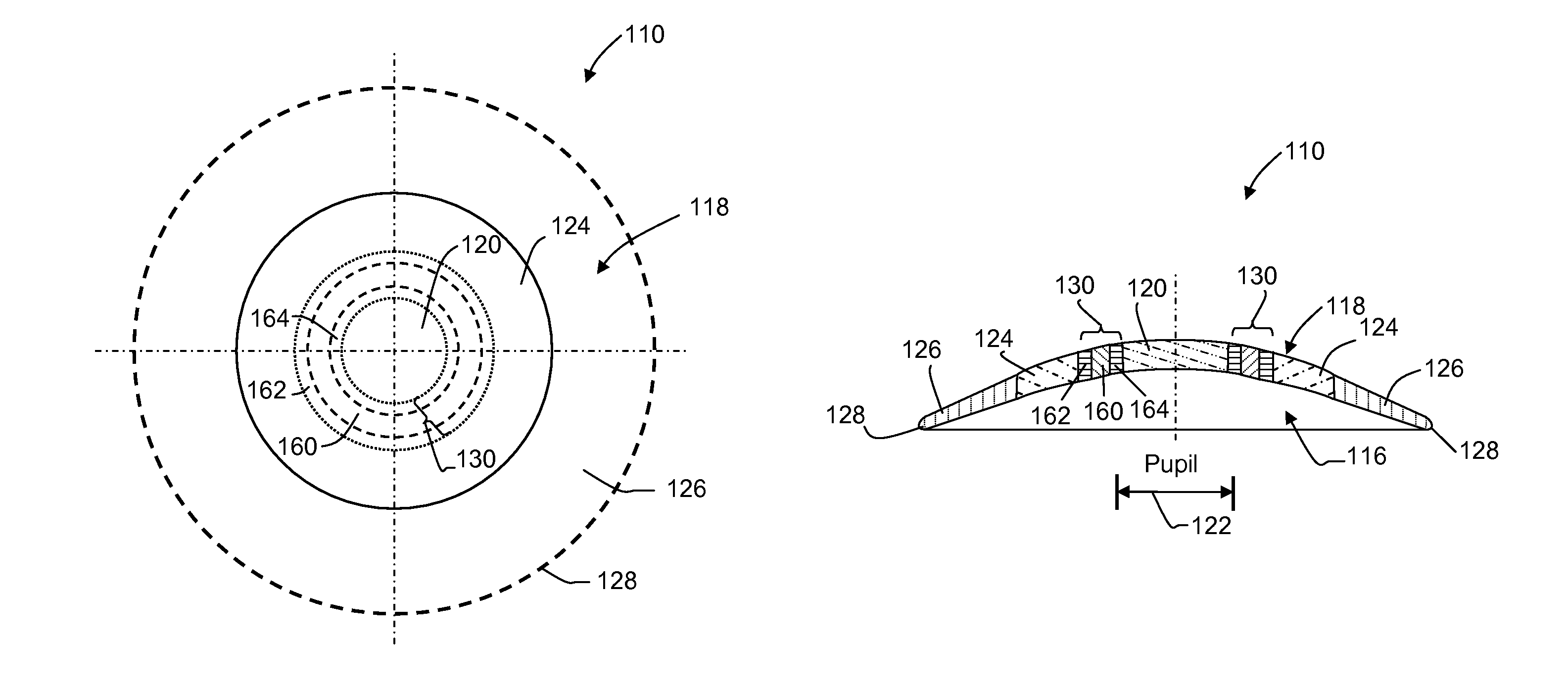
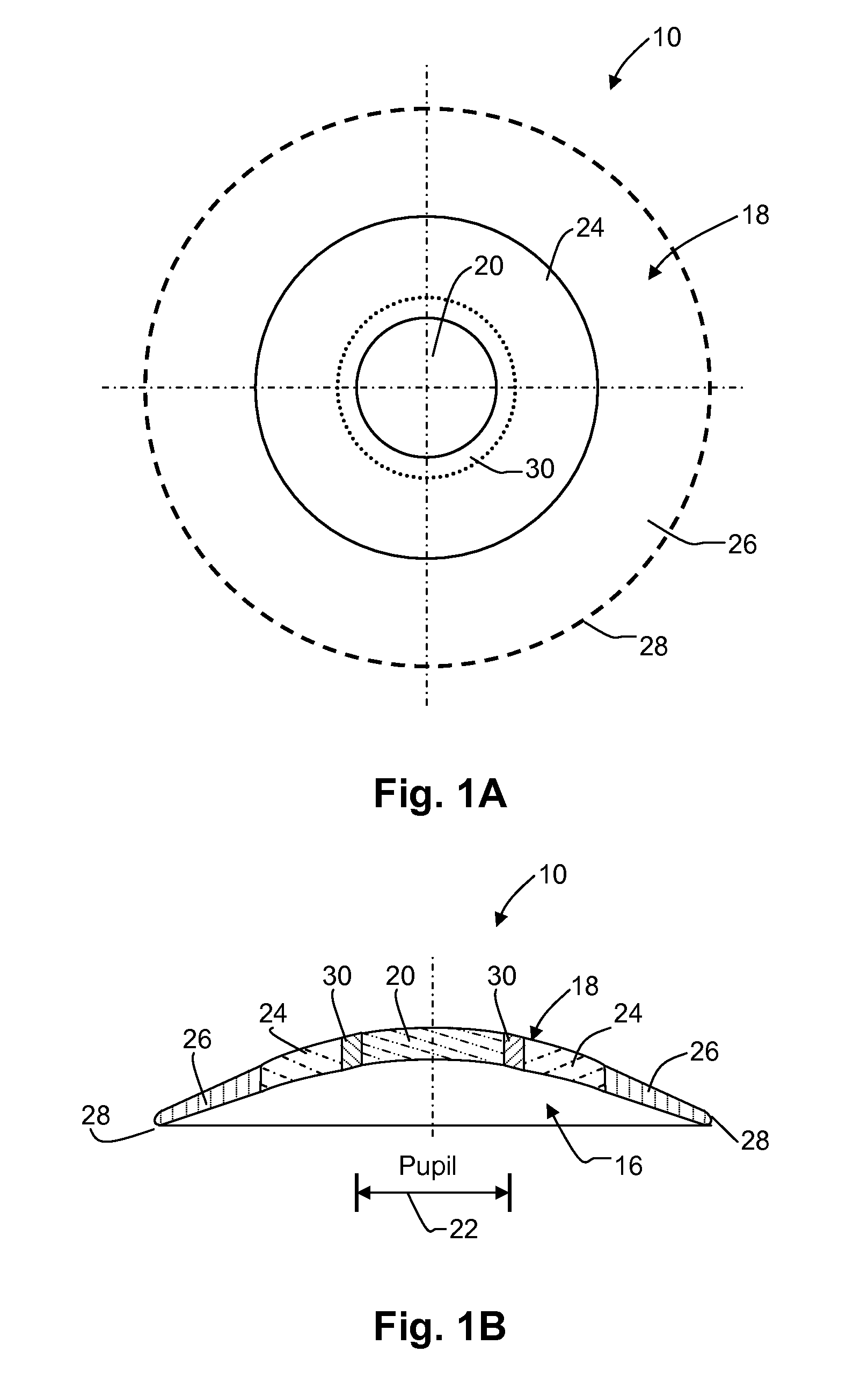
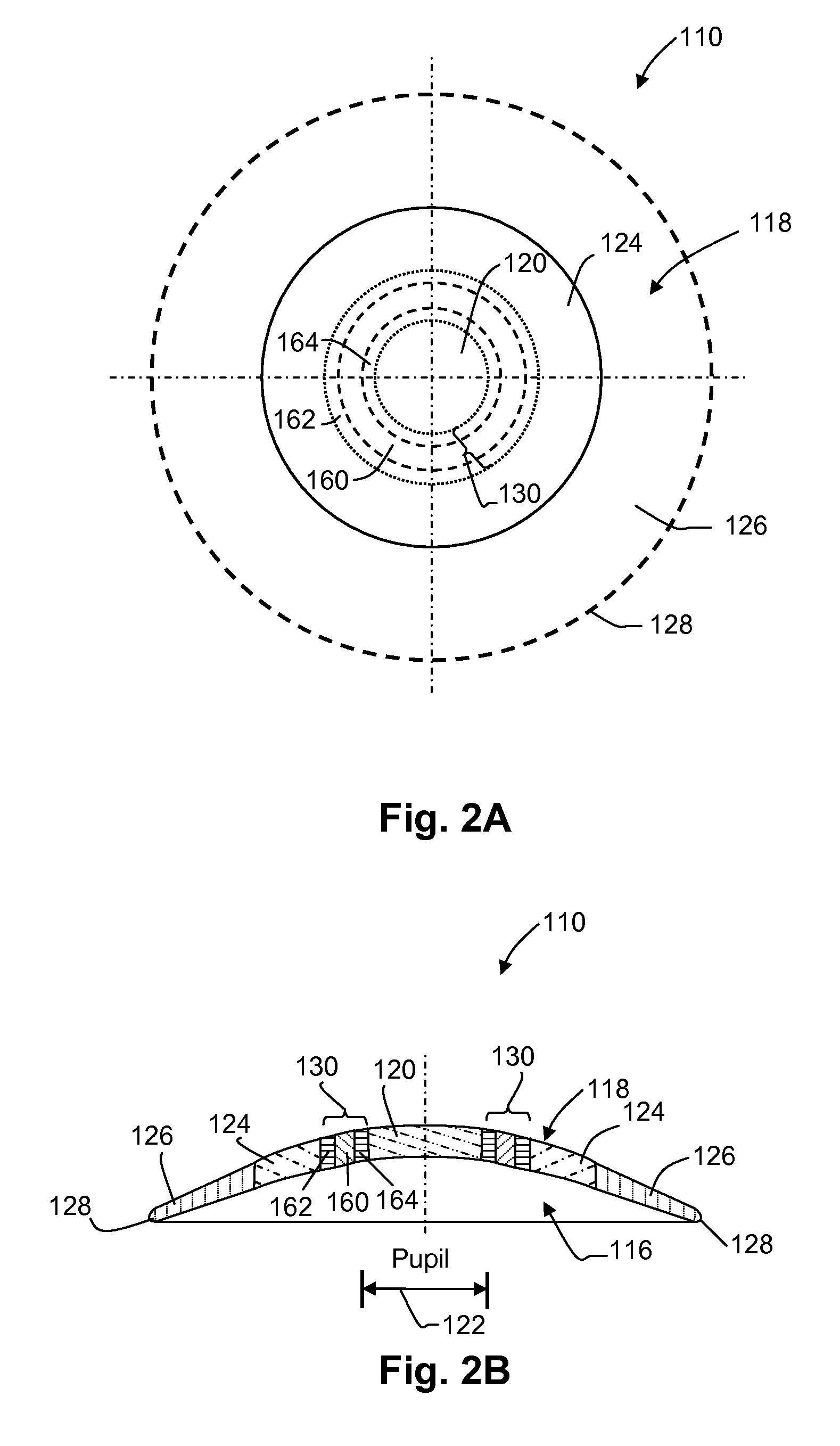
[0031]The first example of a contact lens (generally indicated at 10) formed in accordance with one embodiment of the present invention will now be described making reference to the lens drawings of FIGS. 1A and 1B, the refractive power diagram of FIG. 3 and the sectional eye diagram of FIG. 5 that shows lens 10 in place on the cornea 12 of a myopic human eye 14. As is conventional, lens 10 is molded from a homogeneous transparent plastic material with a selected refractive index, so as to have a rear curved surface 16 that is matched to the shape of cornea 12 of eye 14 and a front curved surface 18. In this case, however, front surface 18 is shaped so that, in combination with the shape of rear surface 16, two optical zones are provided; namely, (i) a central circular optical zone 20 that is substantially equal to, or, in other words, substantially approximates the diameter of a normal pupil (indicated at 22 in FIGS. 1B and 5) of eye 14, and (ii) an annular peripheral optical zone ...


PUM


Abstract

A contact lens (10) for use in controlling or retarding the progression of myopia in an eye has a central optical zone (20) approximating the normal diameter of the pupil of the eye (22) that gives clear central vision at distance for the wearer. An annular peripheral optical zone 24 that is substantially outside the diameter of the pupil is formed around the central optical zone (20) with greater refractive power than that of the central zone (22) so that oblique rays entering the eye through the peripheral optical zone (24) will be brought to focus at a focal plane that is substantially on or anterior to the peripheral region of the retina. Preferably, the rear surface (16) of the lens is shaped to conform to the cornea of the eye and the front surface (18) of the lens (10) is shaped to provide—in conjunction with the rear surface (16)—the desired optical properties of the central and peripheral optical zones. The front surface (18) is also preferably contoured to form a smooth transition (30) between the junction of the central optical zone (20) and the peripheral optical zone (24), with or without designed optical properties such as progressive power.

Description

CROSS-REFERENCE[0001]This application claims benefit of priority from co-pending and commonly assigned Australian provisional patent application No. 2006903112 filed Jun. 8, 2006, the contents of which are incorporated herein by reference in its entirety.FIELD OF THE INVENTION[0002]The present invention relates to means, including methods and contact lenses, suitable for use in controlling or reducing the progression of myopia, particularly though not solely, in the young person.[0003]More particularly, this invention concerns the use of multi-zone, non-multi-focal contact lenses in the treatment of myopia. It represents a novel and unobvious advance over commonly assigned U.S. Pat. No. 7,025,460 by Smith et al., (hereafter “Smith”).[0004]It is understood that a multi-zone contact lens is one where different portions or areas of the lens have different optical properties or functions, most usually different refractive powers or aberration correction functions. Multi-focal contact le...

Claims


Application Information

Patent Timeline
Patent Type & Authority Patents(United States)
IPC IPC(8): G02C7/04
CPCG02C7/042G02C7/04G02C7/044G02C2202/24G02C7/02G02C7/061
Inventor HOLDEN, BRIEN ANTHONYHO, ARTHURSANKARIDURG, PADMAJA RAJAGOPALALLER, THOMAS ARTHURSMITH, III, EARL LEO
Owner THE VISION CRC LTD
Why Eureka
Try Eureka