Printing control apparatus, printing apparatus, and printing method

a control apparatus and printing technology, applied in the direction of printing, other printing apparatus, etc., can solve the problems of image quality deterioration, difficulty in sufficiently suppressing the unevenness caused, and the quality of the printed image might deteriora

Inactive Publication Date: 2015-06-09
CANON KK
View PDF5 Cites 0 Cited by
  • Summary
  • Abstract
  • Description
  • Claims
  • Application Information

AI Technical Summary

Problems solved by technology

It is known when an image is printed using the overlap head, unevenness might occur in a region of the print medium in which the ejection ports arranged in the overlap portions have performed printing and image quality might deteriorate.
The types of unevenness include unevenness caused by errors in the installation positions of the ejection port arrays or errors in the manufacturing process of the ejection ports and unevenness caused by differences in the ejection timing of ink from the ejection ports arranged in the overlap portions of the ejection port arrays.
On the other hand, when an error has occurred in conveying of the print medium between operations of scanning of the print head, a black stripe or a white stripe might be formed at a boundary between a portion printed immediately before the conveying of the print medium and a portion printed immediately after the conveying of the print medium and the quality of the printed image might deteriorate.
Therefore, it is difficult to sufficiently suppress the unevenness caused by the overlap portions of the overlap head using a method for changing density, which is disclosed in Japanese Patent Laid-Open No. 2009-12390.
As the inventors have tried to simultaneously suppress the unevenness that occurs in a region in which the ejection ports in the overlap portions perform printing and the stripe formed in a region in which printing is performed before and after the conveying of the print medium in this manner, a new problem has arisen.

Method used


Image

  • Printing control apparatus, printing apparatus, and printing method
  • Printing control apparatus, printing apparatus, and printing method
  • Printing control apparatus, printing apparatus, and printing method

Examples


first embodiment

[0033]A first embodiment of the present embodiment will be described in detail hereinafter.

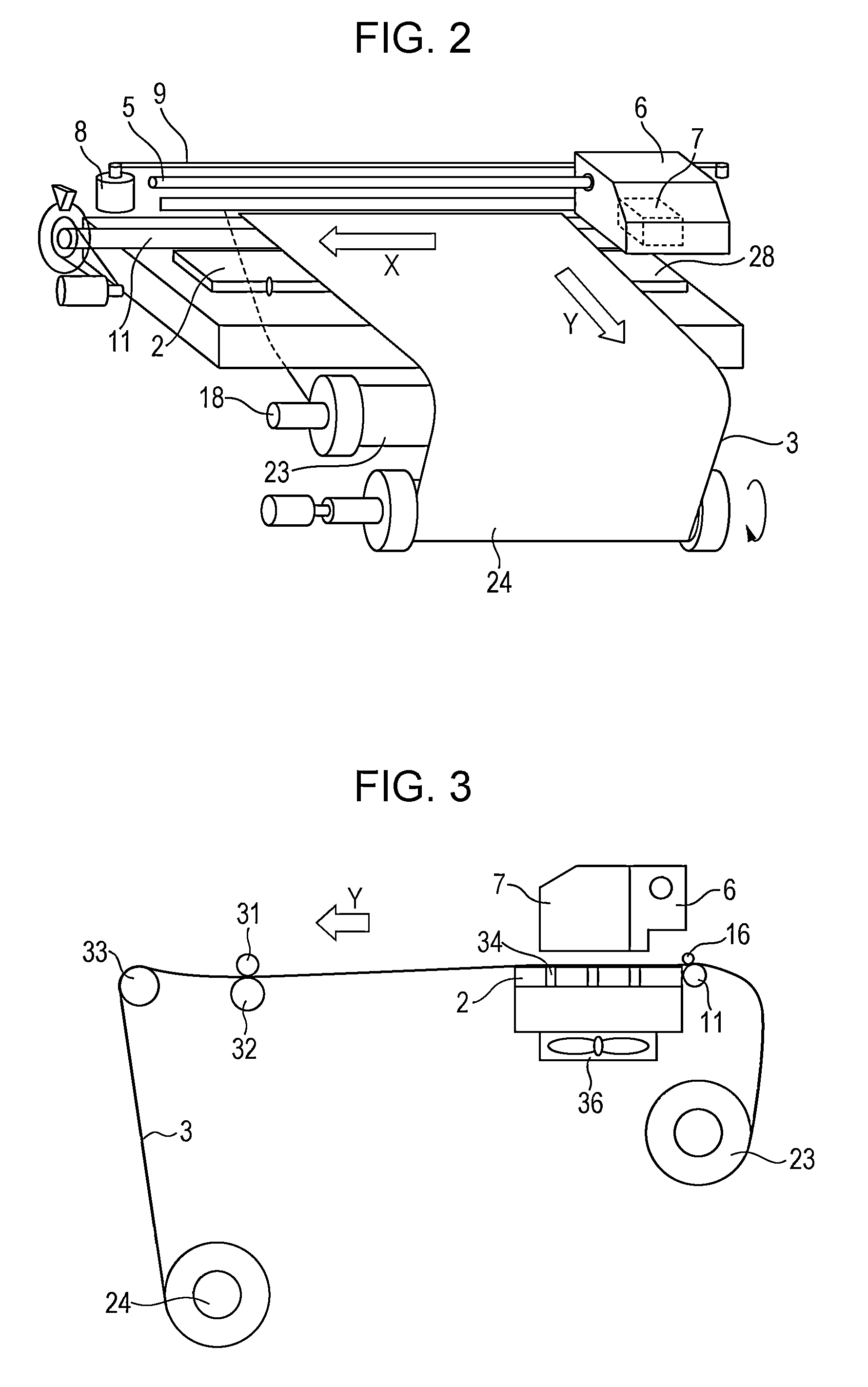
[0034]FIG. 2 is a perspective view illustrating part of the internal configuration of a printing apparatus according to the first embodiment of the present invention. FIG. 3 is a side view illustrating part of the internal configuration of the printing apparatus according to the first embodiment of the present invention.

[0035]A platen 2 is provided inside the printing apparatus, and a multiple of suction holes 34 are formed in the platen 2 in order to suck a print medium 3 onto the platen 2 so that the print medium 3 does not float. These suction holes 34 are connected to ducts, and a suction fan 36 is provided under the ducts. By operating the suction fan 36, the platen 2 sucks the print medium 3.

[0036]A carriage 6 is supported by a main rail 5 extending in a paper width direction and configured in such a way as to be able to reciprocally move in an X direction. The carriage 6 includes an ove...

second embodiment

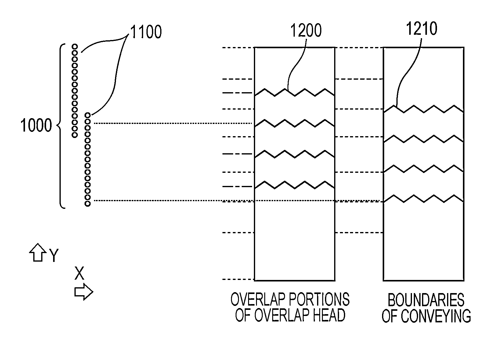
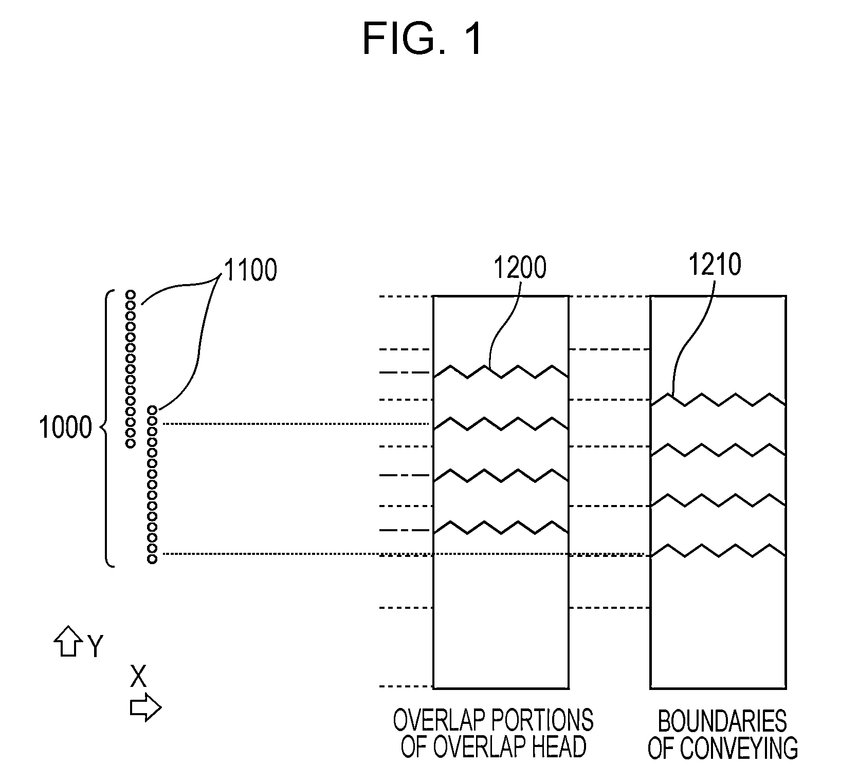
[0091]In the first embodiment, a mode has been described in which the shape of a boundary between images printed by two ejection port arrays in the overlap portion 53 and the shape of a boundary between images printed by different operations of print scanning are the same but the phases of these boundaries are different.

[0092]In a second embodiment, a mode will be described in which the amounts of changes (hereinafter also referred to as amplitudes) of two boundaries at positions in the Y direction are different.

[0093]As in the first embodiment, a mode will be described in this embodiment in which a complete image is formed in the unit region 76 of the print medium 3 by three operations of print scanning.

[0094]In this embodiment, as in the first embodiment, the mask patterns illustrated in FIGS. 8A and 8B are used for the first ejection port array 35a and the second ejection port array 35b in the overlap portion 53 and the area around the overlap portion 53.

[0095]That is, in the mas...


PUM


Abstract

A printing apparatus performs printing using a print head in which a plurality of ejection port arrays are arranged in such a way as to form overlap portions. Ink is ejected such that a shape of a first boundary between images printed in a first unit region by ejection ports of a first ejection port array and a second ejection port array in an overlap portion and a shape of a second boundary between images printed in a second unit region in first and second operations of scanning continuously change in an array direction as positions of the first and second boundaries change in a cross direction and the shape of the second boundary becomes different from the shape of the first boundary.

Description

BACKGROUND OF THE INVENTION[0001]1. Field of the Invention[0002]The present invention relates to a printing control apparatus, a printing apparatus, and a printing method.[0003]2. Description of the Related Art[0004]A printing apparatus that forms an image on a print medium by ejecting ink onto the print medium while scanning a print head including a plurality of ejection port arrays in which a plurality of ejection ports that eject ink of the same color are arranged in a certain array direction is known. The plurality of ejection port arrays are arranged in a direction crossing to the array direction of the ejection ports, and the print head is scanned in the direction crossing to the array direction of the ejection ports.[0005]In these years, it is desired to improve the printing speed of such a printing apparatus, and the length of the print head is being increased to achieve this goal. In one of known methods for increasing the length of the print head, a print head (hereinafter...

Claims


Application Information

Patent Timeline
Patent Type & Authority Patents(United States)
IPC IPC(8): B41J29/38B41J2/155B41J2/21B41J2/15
CPCB41J2/2146
Inventor MARUMOTO, YOSHITOMOYAMAGUCHI, HIROMITSUTSUBOI, HITOSHIKATO, RYOTAUSHIYAMA, TAKAYUKI
Owner CANON KK
Why Eureka
Try Eureka