Vacuum pulldown of print medium in printing system

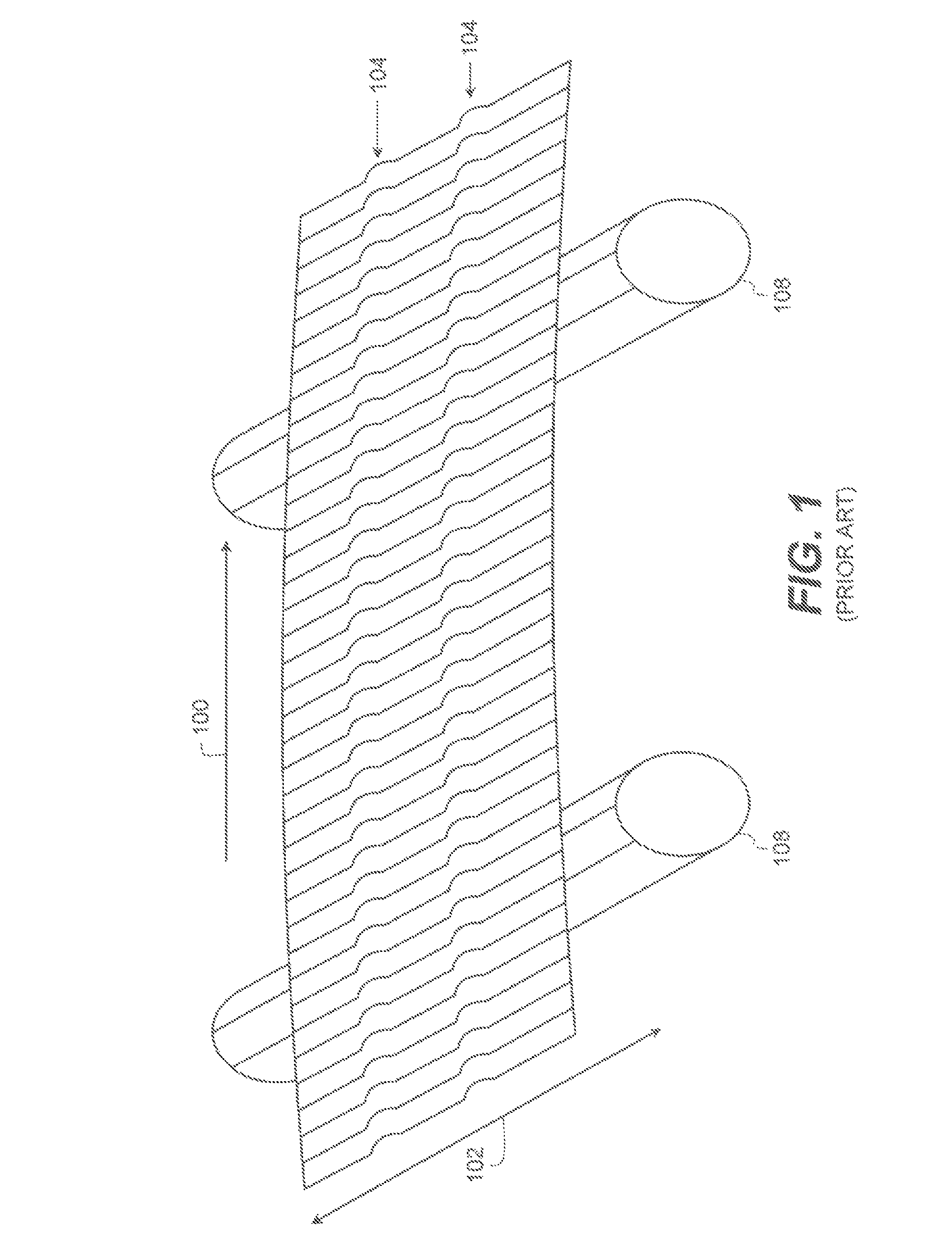
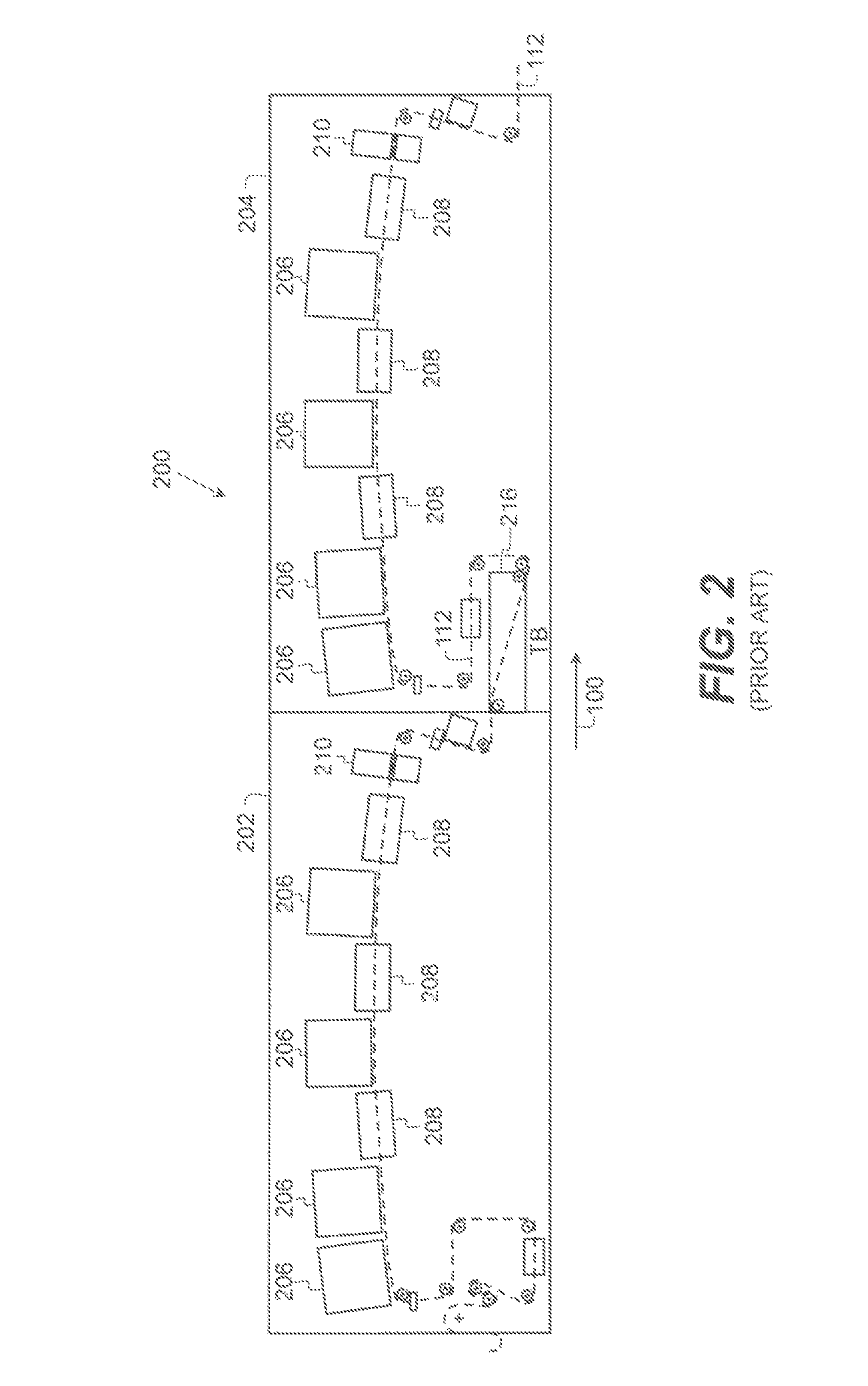
a vacuum pulldown and print medium technology, applied in printing, typewriters, other printing apparatuses, etc., can solve the problems of significant hysteresis, significant moisture content in the print medium, and print medium expansion, so as to prevent reduce the formation of flutes or wrinkles, and limit the smearing of wet ink.

Active Publication Date: 2015-06-09
EASTMAN KODAK CO
View PDF21 Cites 0 Cited by
  • Summary
  • Abstract
  • Description
  • Claims
  • Application Information

AI Technical Summary

Benefits of technology

[0009]Increasing the wrap angle of the print medium around the aligned transport roller has many advantages including preventing the print medium from fluttering or vibrating up and down in the print zone, limiting the smearing of wet ink on the print medium due to contact with the linehead or its support structure, and reducing the formation of flutes or wrinkles that can cause hard creases and other print defects in the print medium.

Problems solved by technology

The jetting of liquid onto the print medium introduces significant moisture content to the print medium, particularly when the system is used to print multiple colors on a print medium.
Due to its moisture content, the print medium expands and contracts in a non-isotropic manner often with significant hysteresis.
The continual change of dimensional characteristics of the print medium often adversely affects image quality.
Although drying is used to remove moisture from the print medium, drying too frequently, for example, after printing each color, also causes changes in the dimensional characteristics of the print medium that often adversely affects image quality.
This can result in localized buckling of the print medium away from the roller to create lengthwise ripples, also called flutes or wrinkles, in the print medium.
This wrinkling of the print medium during the printing process often leads to permanent creases forming in the print medium that ultimately affect image quality and are considered a print defect.
It is not uncommon for the bottom face of the support structure to become wet, either due to condensation from the moist air produced by the printing process or due to mist drops created by the print drops striking the print medium.
The result is a degradation of the print quality.

Method used


Image

  • Vacuum pulldown of print medium in printing system
  • Vacuum pulldown of print medium in printing system
  • Vacuum pulldown of print medium in printing system

Examples


Embodiment Construction

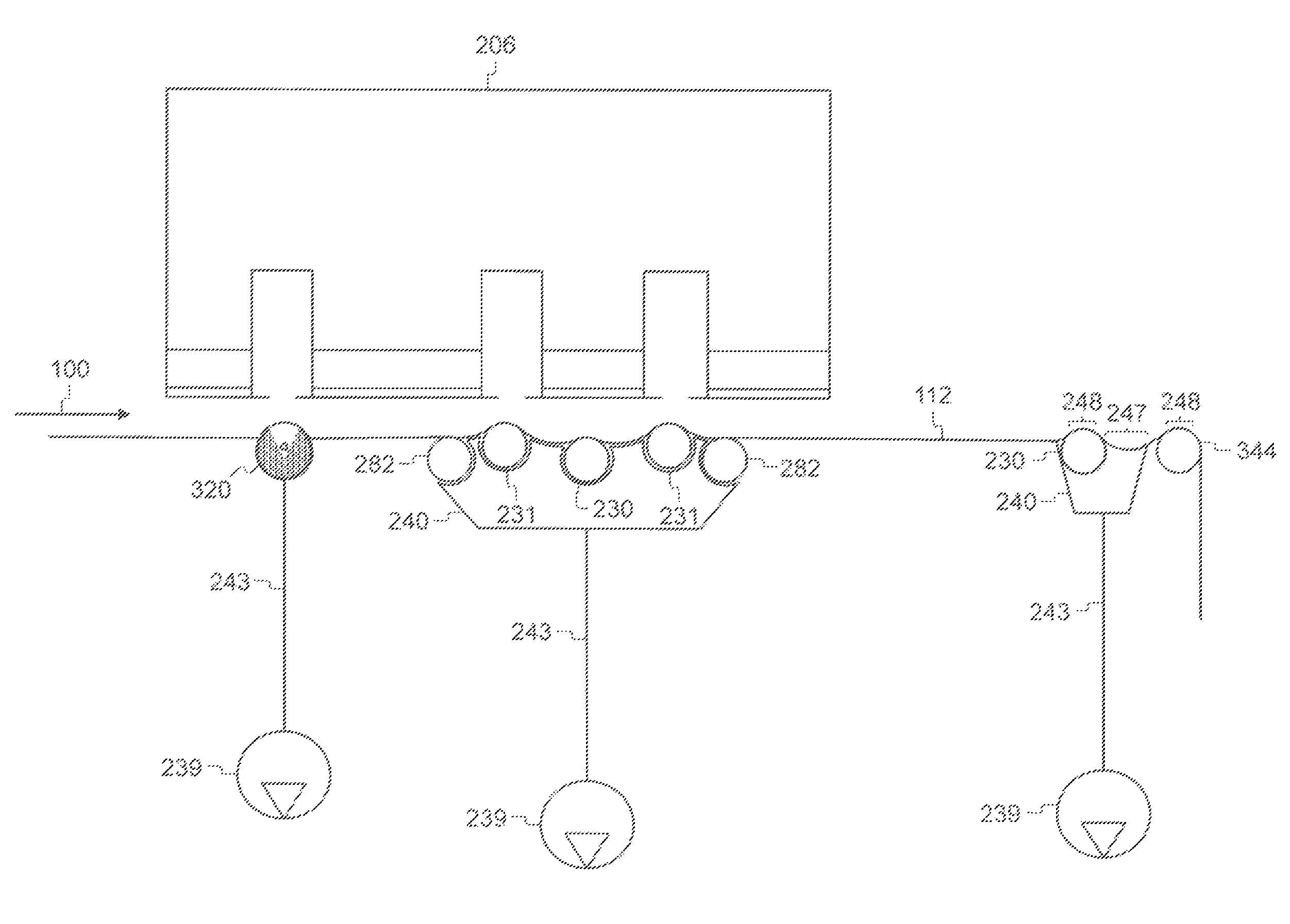
[0030]The present description will be directed in particular to elements forming part of, or cooperating more directly with, a web transport system. It is to be understood that elements not specifically shown, labeled, or described can take various forms well known to those skilled in the art. In the following description and drawings, identical reference numerals have been used, where possible, to designate identical elements. It is to be understood that elements and components can be referred to in singular or plural form, as appropriate, without limiting the scope of the invention.

[0031]The example aspects of the present invention are illustrated schematically and not to scale for the sake of clarity. One of ordinary skill in the art will be able to readily determine the specific size and interconnections of the elements of the example aspects of the present invention.

[0032]As described herein, the example aspects of the present invention provide a printhead or printhead componen...


PUM


Abstract

A method for printing on a print medium is disclosed. The method includes providing a linehead defining one or more print zones and adapted to jet liquid onto the print medium. One or more vacuum transport rollers having a porous sleeve rotatable around a non-rotating core are also provided. At least one vacuum transport roller is disposed adjacent to the second side of the movable print medium, opposite the first linehead, and aligned with a print zone. The core includes a vacuum manifold that outputs a vacuum force that operates on the print medium through the porous sleeve. The print medium is moved through the printing system and a vacuum force deflects the print medium, causing an increase in a wrap angle of the print medium around the vacuum transport roller. Liquid is jetted from the linehead onto the print medium to form a print.

Description

CROSS REFERENCE TO RELATED APPLICATIONS[0001]Reference is made to commonly-assigned, U.S. patent applications Ser. No. 14 / 040,843, entitled “INTEGRATED VACUUM ASSIST WEB TRANSPORT SYSTEM”, Ser. No. 14 / 040,843, entitled “VACUUM PULLDOWN OF PRINT MEDIUM IN PRINTING SYSTEM”, and Ser. No. 14 / 040,854, entitled “VACUUM TRANSPORT ROLLER FOR WEB TRANSPORT SYSTEM”, all filed concurrently herewith.[0002]Reference is also made to commonly-assigned, U.S. patent application Ser. No. 13 / 483,368, entitled “VACUUM PULLDOWN OF A PRINT MEDIUM IN A PRINTING SYSTEM” filed May 30, 2012 and commonly-assigned, U.S. patent application Ser. No. 13 / 483,356, entitled “VACUUM PULLDOWN OF A PRINT MEDIUM IN A PRINTING SYSTEM” filed May 30, 2012.FIELD OF THE INVENTION[0003]The invention relates generally to the field of digitally controlled printing systems, and more particularly to transporting a print medium through a printing system. Still more particularly, the present invention relates to the use of a vacuum...

Claims


Application Information

Patent Timeline
Patent Type & Authority Patents(United States)
IPC IPC(8): B41J2/01B41J11/00B41J29/377
CPCB41J11/0085B41J29/377B41J3/543B41J11/04
Inventor PIATT, MICHAEL J.KATERBERG, JAMES A.VANDAGRIFF, RANDY D.
Owner EASTMAN KODAK CO
Why Eureka
Try Eureka