
Ventilation system and control thereof

a ventilation system and control technology, applied in the field of ventilation systems, can solve the problems of not meeting the requirements of construction and use, unable to meet the requirements of emergency or rapid response conditions, and the use of mechanical ventilators is rare, so as to overcome or ameliorate the disadvantages

Inactive Publication Date: 2015-07-07
RESMED LTD
View PDF65 Cites 8 Cited by
  • Summary
  • Abstract
  • Description
  • Claims
  • Application Information

AI Technical Summary

Benefits of technology

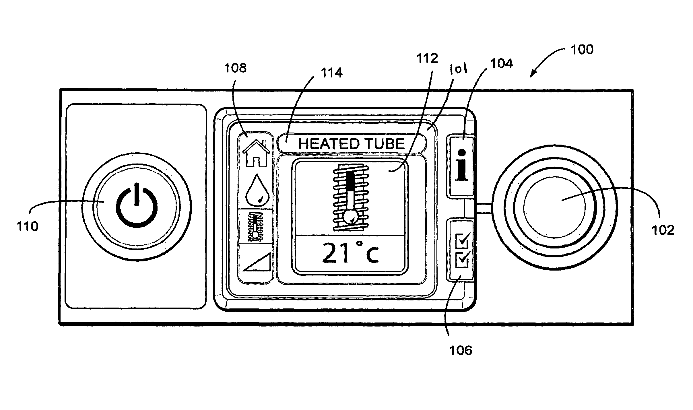
The present invention provides an alternative ventilation system arrangement and a multifunction control member for use in emergency situations. The ventilator device includes a display screen to display a plurality of functions and parameters associated with the functions, and a finger-operable dial that can be manipulated in two ways to select and scroll between the parameters. The device can generate pressurized gas for treatment of breathing disorders and can be used in various other applications. The user interface allows for easy selection and manipulation of the ventilator functions and parameters. Overall, the invention provides a more convenient and efficient ventilation system.

Problems solved by technology

Further, some troubles require feeding the patient with a controlled volume of breathable gas, such as for neuromuscular patients.
Mechanical ventilators are rarely used in emergency situations due to their larger size, complexity and time required to set-up such devices.
Mechanical ventilators are predominantly used in hospitals or for long term care as they are generally large and complex.
None of these prior art devices provides an entirely satisfactory solution to the provision of emergency ventilation to the patient, nor to ease of construction and use requirements required under such emergency or rapid response conditions.

Method used


Image

  • Ventilation system and control thereof
  • Ventilation system and control thereof
  • Ventilation system and control thereof

Examples


Embodiment Construction

[0032]The following description is provided in relation to several embodiments which may share common characteristics and features. It is to be understood that one or more features of any one embodiment may be combinable with one or more features of the other embodiments. In addition, any single feature or combination of features in any of the embodiments may constitute an additional embodiment.

[0033]In this specification, the word “comprising” is to be understood in its “open” sense, that is, in the sense of “including”, and thus not limited to its “closed” sense, that is the sense of “consisting only of”. A corresponding meaning is to be attributed to the corresponding words “comprise, comprised and comprises where they appear.

[0034]Ventilator Device

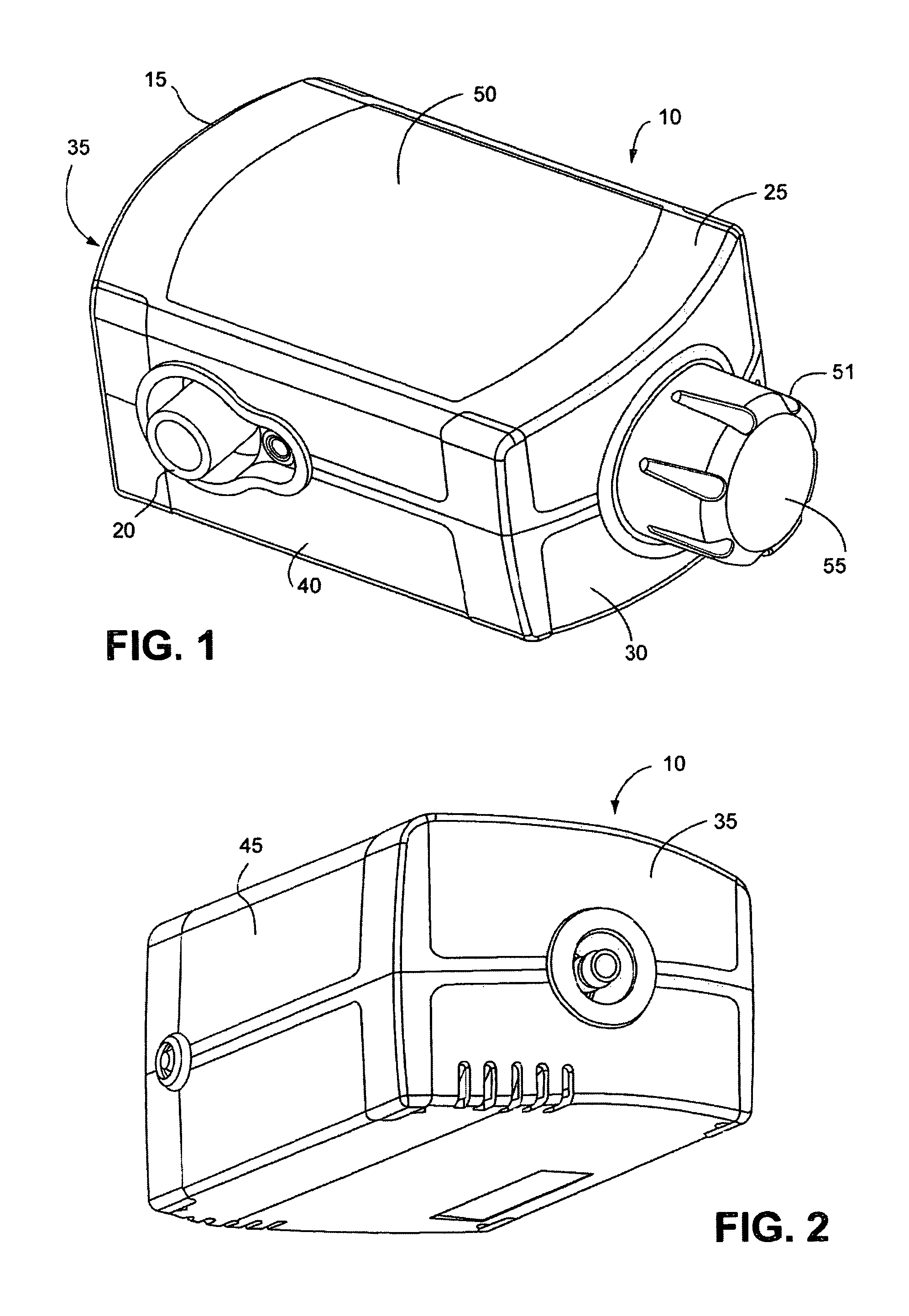
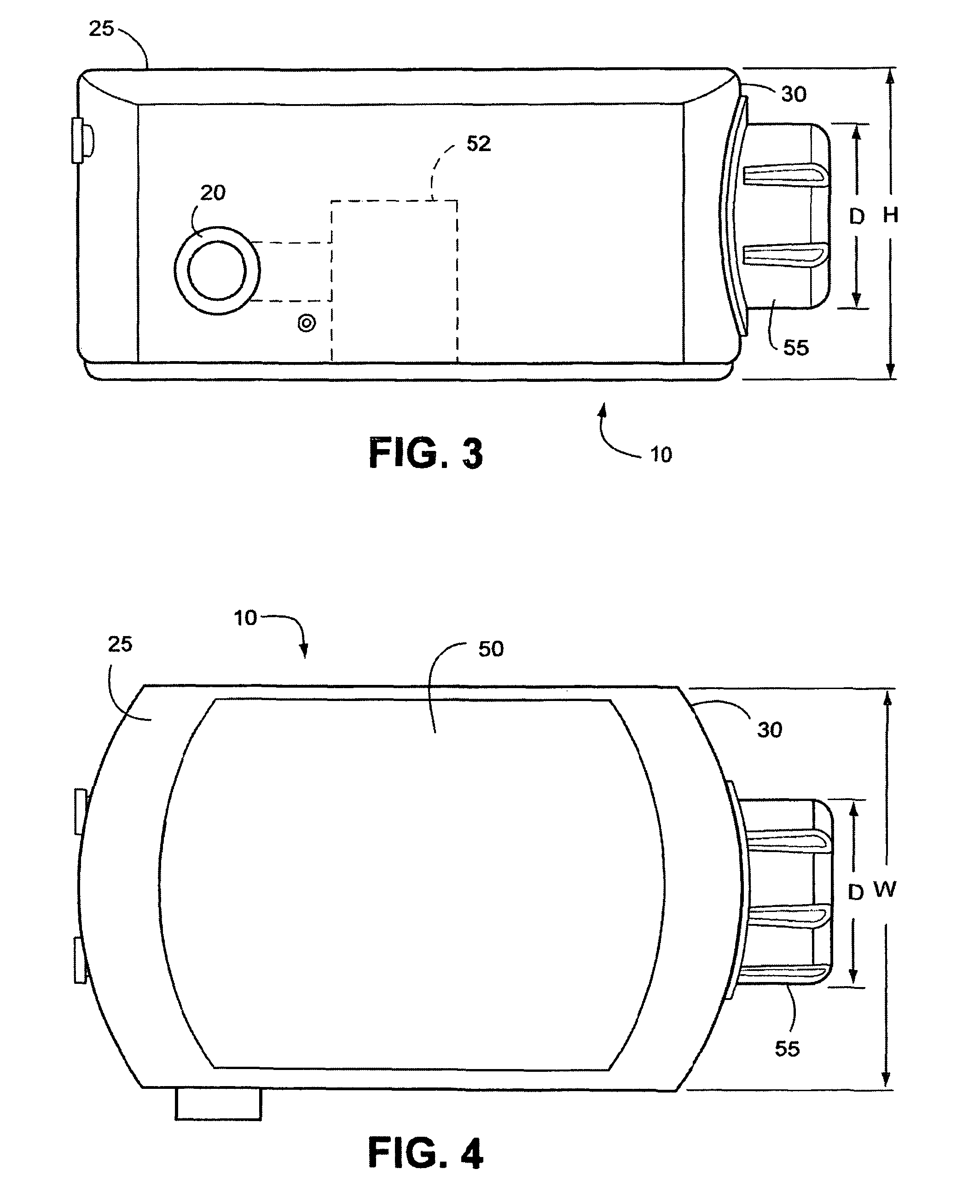
[0035]FIGS. 1-4 illustrate an embodiment of a ventilator device 10 to enhance an emergency paramedic's efforts in emergency situations. In general the ventilator is a small, light and portable. The ventilator device can also have more ...


PUM


Abstract

A ventilator device (10) includes a display screen (50, 101) to display a plurality of ventilator functions / modes (or menus) and a plurality of parameters (or sub-menus) associated with at least one of said ventilator functions / modes. A control member, e.g., in the form of a multifunction finger-operable dial (55, 102) is provided to select from the plurality of ventilator functions / modes and / or parameters, the dial being manipulatable in a first manner (e.g., rotation) to scroll between said parameters, and being manipulatable in a second manner (e.g., touching, pressing and / or depressing) to select one of the ventilator functions / modes and / or parameters.

Description

CROSS REFERENCE TO RELATED APPLICATIONS[0001]This application is the U.S. national phase of International Application No. PCT / AU2008 / 001638 filed Nov. 5, 2008, which designated the U.S. and claims the benefit of Australian Provisional Application No. 2007906080 filed on Nov. 5, 2007, Australian Provisional Application No. 2007906444, filed Nov. 26, 2007, Australian Provisional Application No. 2008904835, filed Sep. 17, 2008 and Australian Provisional Application No. 2008905107, filed Oct. 1, 2008, each of which is incorporated herein in its entirety.BACKGROUND OF THE INVENTION[0002]1. Field of the Invention[0003]The present invention relates to ventilation systems used to treat respiratory disorders or diseases. Ventilation systems includes invasive and non-invasive ventilation, Continuous Positive Airway Pressure (CPAP), Bilevel therapy and treatment for sleep disordered breathing (SDB) conditions such as Obstructive Sleep Apnea (OSA), and for various other respiratory disorders an...

Claims


Application Information

Patent Timeline
Patent Type & Authority Patents(United States)
IPC IPC(8): F16K31/02F23D14/00H05B3/00A61M16/10F23D11/00F24J3/00A62B18/02A61M16/00A61M15/00A62B7/00A61M16/16
CPCA61M16/0051A61M16/1095A61M16/16A61M2016/0027A61M2016/0036A61M2205/505A61M2205/52A61M2205/8206A61M2205/8237A61M2205/8262A61M16/024A61M16/0069A61M2205/18A61M2205/584A61M16/0003
Inventor BERTINETTI, MARKWAWRZONEK, DAVID PETERHILL, PHOEBE KATHERINEPRIMROSE, ROHAN NEILTHIELE, HEIKEVIRR, ALEXANDERBATH, ANDREW RODERICKCURTIS, SANDRA ROBYNPRICE, ANDREW MIKAEL
Owner RESMED LTD
Learn More