Concealed knife system

a concealed knife and sheath technology, applied in the field of concealed knife sheaths, can solve the problems of giving away the presence of concealed weapons, and achieve the effect of quick pulling out of the sheath

Active Publication Date: 2015-08-04
VANHETEREN WILLIAM J
View PDF17 Cites 8 Cited by
  • Summary
  • Abstract
  • Description
  • Claims
  • Application Information

AI Technical Summary

Problems solved by technology

One of the common methods of concealing a knife is to incorporate it into a belt buckle, but this often results in a buckle which is large and conspicuous, thus giving away the presence of a concealed weapon.

Method used


Image

  • Concealed knife system
  • Concealed knife system
  • Concealed knife system

Examples


Embodiment Construction

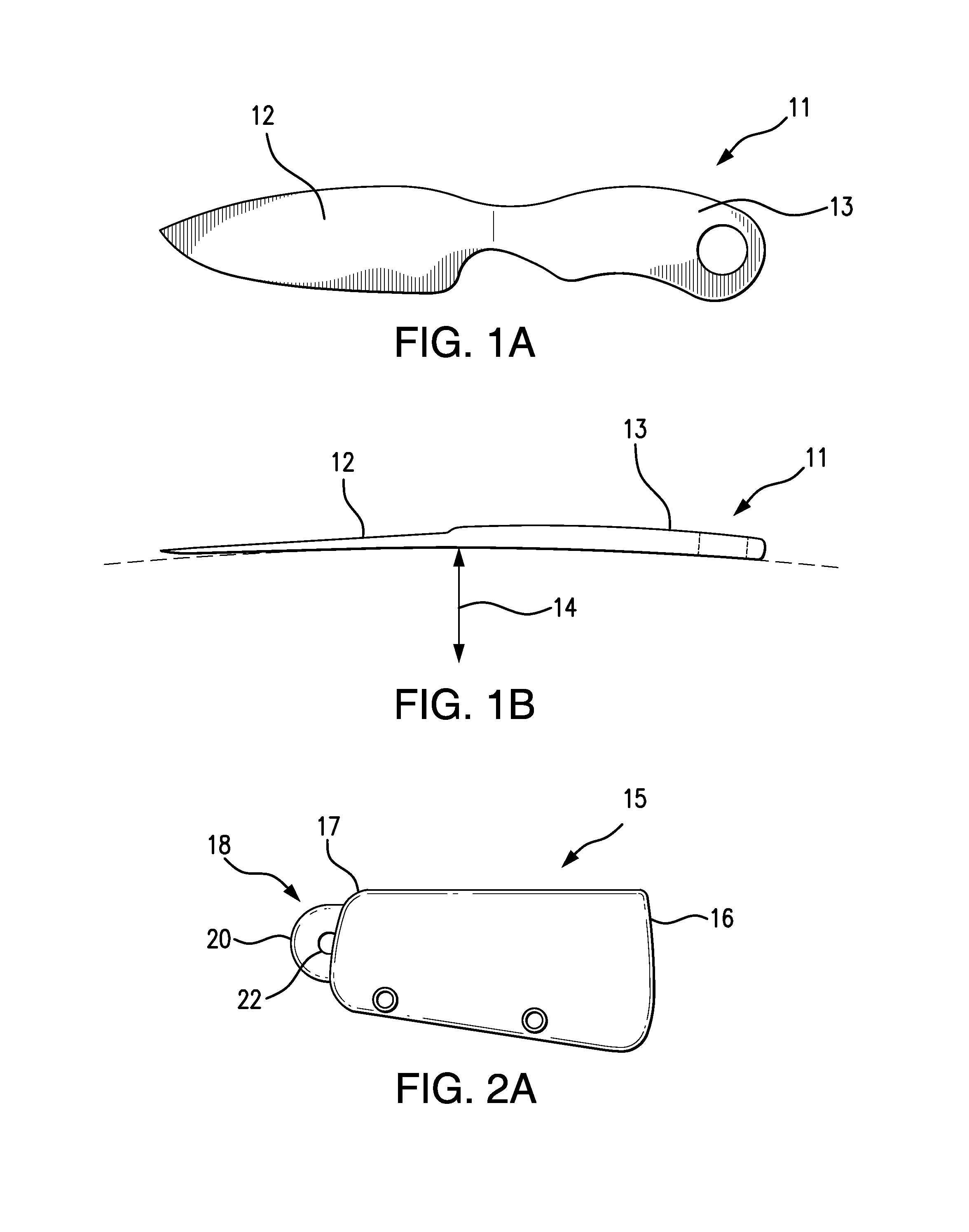
[0027]Referring to FIGS. 1A and 1B, the fixed blade knife 11 comprises a blade 12 and handle 13 manufactured as an integral unit. The knife 11 has a radius of curvature 14 corresponding to the circumference of the belt, so as to conform to the waist contours of the wearer for optimum concealment.

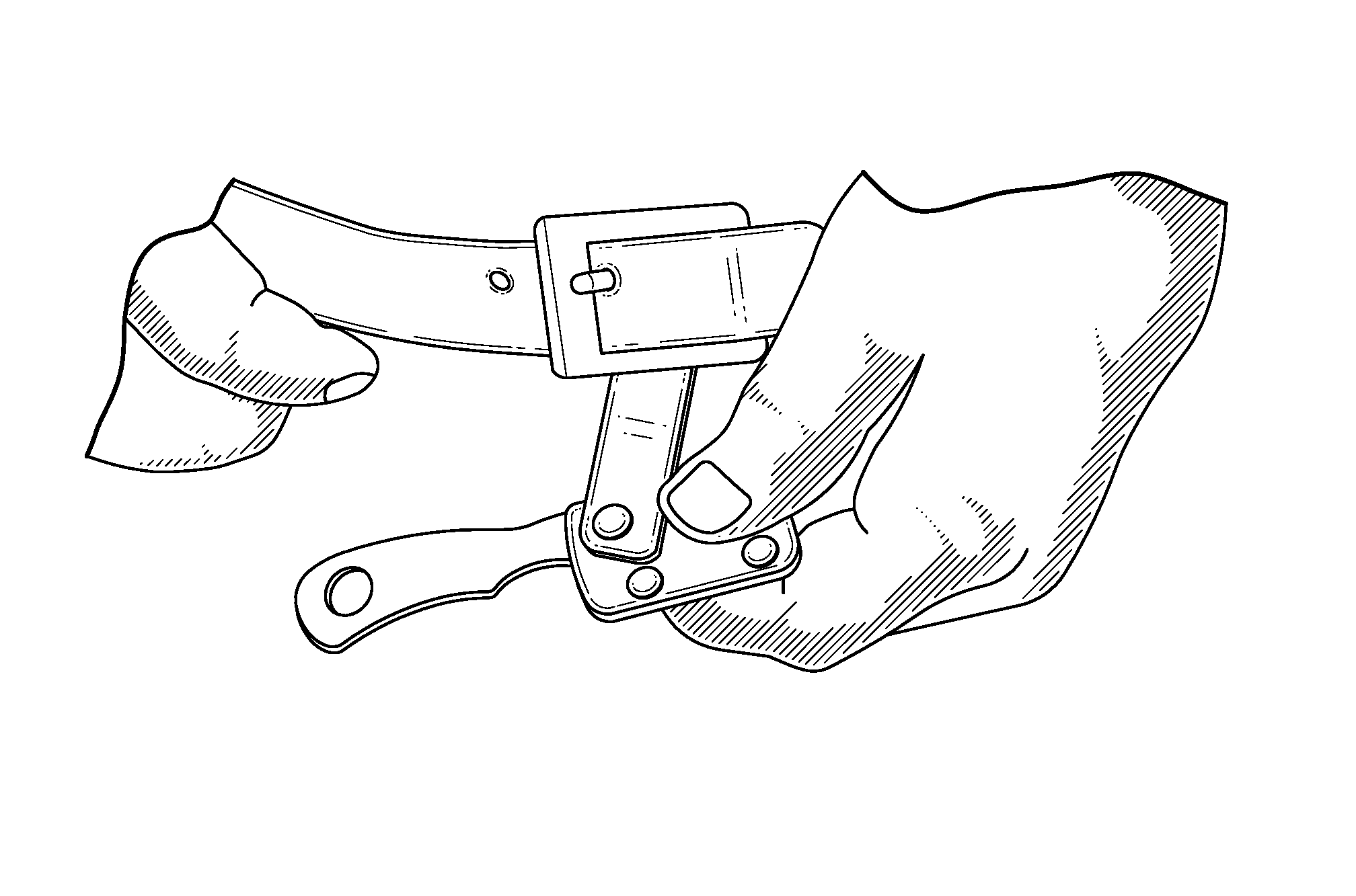
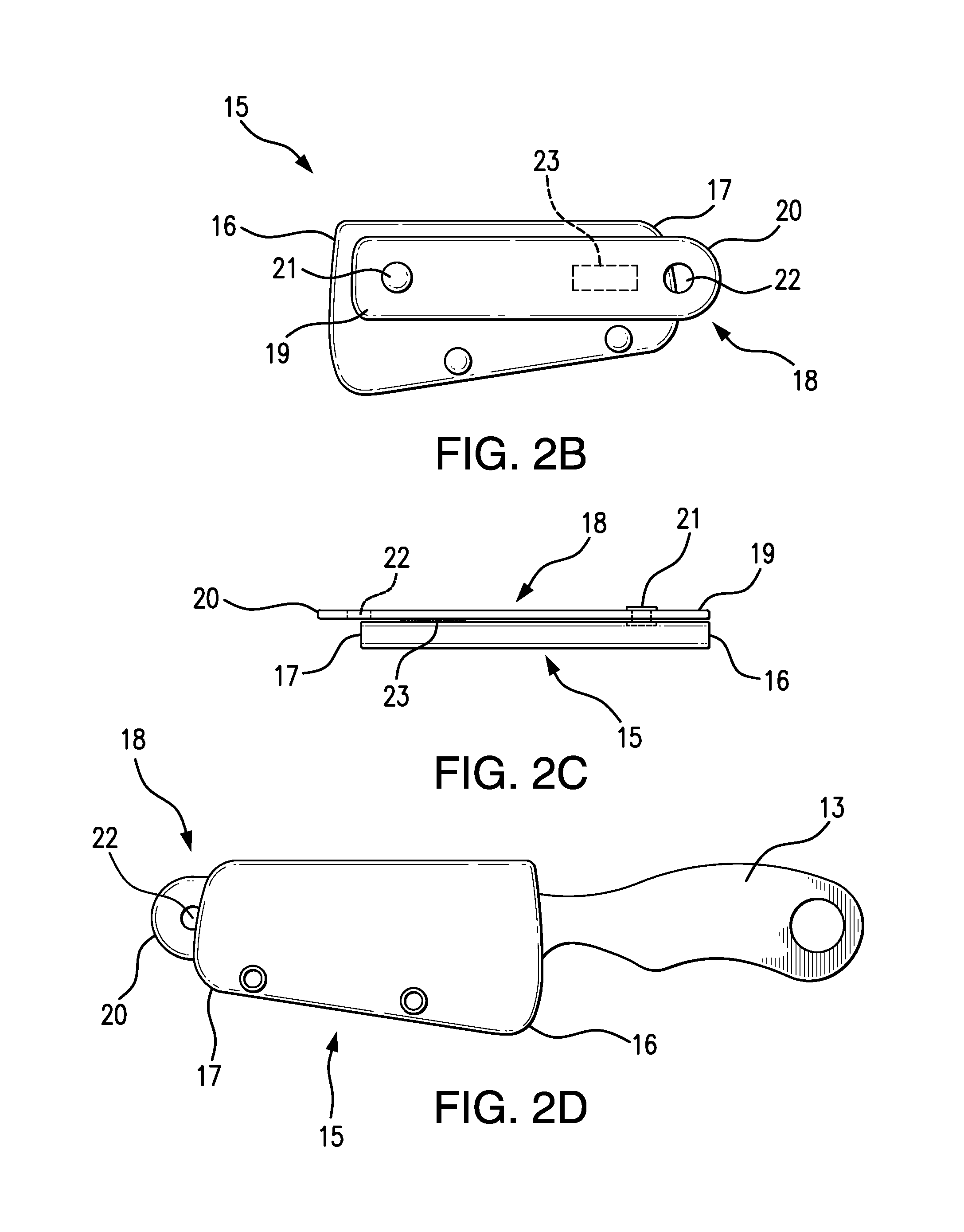
[0028]FIGS. 2A-2D depict the sheath 15, which has an open end 16 and a closed end 17. A retaining strap 18 is attached at its proximal end 19 to the open end 16 of the sheath 15 by means of a swivel joint 21, about which the strap 18 and sheath 15 can mutually rotate with respect to one another. The distal end 20 of the retaining strap 18 has an aperture 22 sized to slide over the buckle tongue. Cooperating hook-and-loop fasteners 23 on the sheath 15 and retaining strap 18 secure them in alignment so that the knife 11 does not drop from behind the belt.

[0029]FIGS. 3A-3D depict the process by which the belt buckle is opened, the retaining strap 18 is rotated into position, and the buckle tong...


PUM


Abstract

A method of concealing a fixed blade knife inconspicuously behind a trouser belt utilizes a rotating sheath connected by a strap to the tongue of the belt buckle. The sheath is concealed behind the belt by pushing it upward into alignment with the strap and is deployed by pushing it downward out of alignment with the strap. The knife is curved so as to conform to the contours of the wearer's waist.

Description

REFERENCE TO RELATED APPLICATION[0001]This Application claims the benefit of the filing date of Provisional Patent Application No. 61 / 965,459, filed on Jan. 30, 2014.FIELD OF INVENTION[0002]The present invention relates to the field of knife sheaths, and more particularly to concealable knife sheaths.BACKGROUND OF THE INVENTION[0003]Small knives may be carried on the person for purposes of self-defense or by military and law enforcement personnel. It is often desirable to conceal such knives, lest an assailant noticing its location attempt to seize it. One of the common methods of concealing a knife is to incorporate it into a belt buckle, but this often results in a buckle which is large and conspicuous, thus giving away the presence of a concealed weapon.[0004]Along with inconspicuous concealment, there is also a need to conceal the knife so that it is readily and quickly deployable. The present invention provides a method of unobtrusively concealing a knife behind a standard trou...

Claims


Application Information

Patent Timeline
Patent Type & Authority Patents(United States)
IPC IPC(8): B26B29/02A45F5/00A45F5/02A44B11/00
CPCA45F5/021B26B29/02B26B29/025A45F2200/0591A44B11/005F41C33/048
Inventor VANHETEREN, WILLIAM J
Owner VANHETEREN WILLIAM J
Why Eureka
Try Eureka