Structure for mounting piston ring

a technology for mounting structures and piston rings, which is applied to trunk pistons, machines/engines, and plungers, etc., can solve the problems of scuffing phenomenon on pistons, fouling and degradation of pistons after treatment, etc., and achieve the effect of reducing blowing gas

Inactive Publication Date: 2015-08-18
HYUNDAI MOTOR CO LTD
View PDF25 Cites 1 Cited by
  • Summary
  • Abstract
  • Description
  • Claims
  • Application Information

AI Technical Summary

Benefits of technology

[0012]Accordingly, the present invention has been made keeping in mind the above problems occurring in the related art, and the present invention attempts to propose a structure for mounting a piston ring, which when a plurality of piston rings is mounted around a piston head, allows end gaps formed in the piston rings to rotate at different sections in a circumferential direction of the piston head, thereby preventing the end gaps from being aligned in a line and thus reducing a blow-by gas.
[0018]According to the present invention, the guide protrusion is provided within a section of the guide recess such that the guide protrusion is adjacent the end gap of the piston ring, so that respective rotation sections of the end gaps of the respective piston rings do not overlap with each other even when the piston rings are rotated, thereby having the effect of reducing blow-by gas.

Problems solved by technology

However, when end gaps of the piston rings coincide with each other during rotating operation, an amount of blow-by gas considerably increases to cause turbo fouling and degradation in post-treatment.
However, in this case, since the piston rings cannot rotate, one-sided wear of a piston and adhesion of piston rings occur and therefore a scuffing phenomenon occurs on the piston.

Method used


Image

  • Structure for mounting piston ring
  • Structure for mounting piston ring
  • Structure for mounting piston ring

Examples


Embodiment Construction

[0027]Reference will now be made in detail to various embodiments of the present invention(s), examples of which are illustrated in the accompanying drawings and described below. While the invention(s) will be described in conjunction with exemplary embodiments, it will be understood that present description is not intended to limit the invention(s) to those exemplary embodiments. On the contrary, the invention(s) is / are intended to cover not only the exemplary embodiments, but also various alternatives, modifications, equivalents and other embodiments, which may be included within the spirit and scope of the invention as defined by the appended claims.

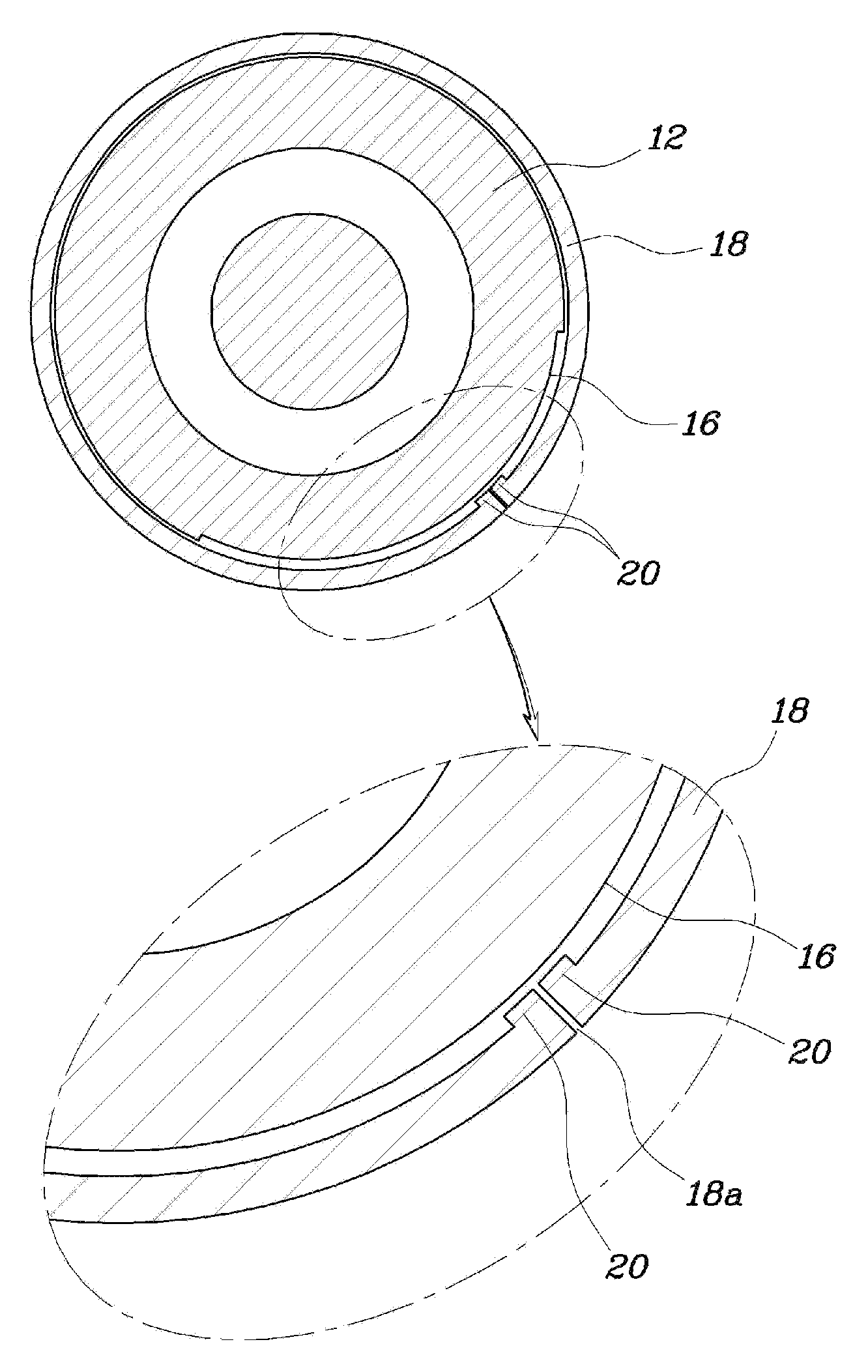
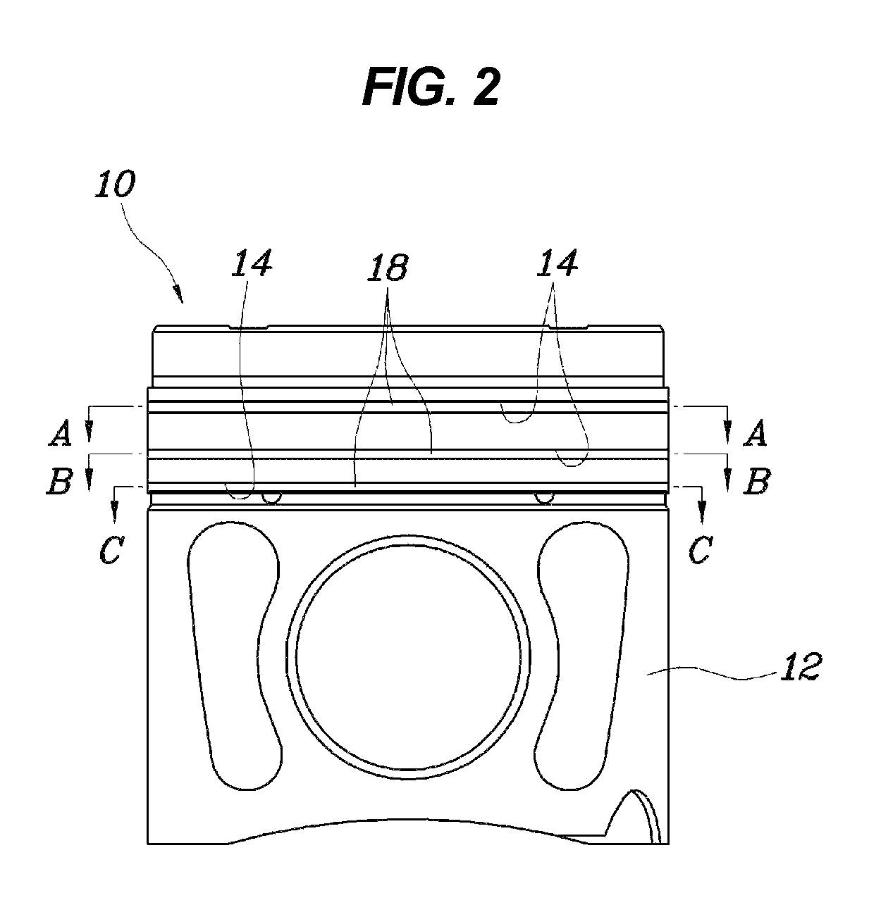
[0028]A structure for mounting a piston ring shown in FIGS. 2 to 7 generally includes a mounting structure for a piston 10 and the piston ring 18.

[0029]Specifically, the piston 10 includes a ring groove 14 in a circumferential direction, and the ring groove is provided in an outer wall thereof with a guide recess 16 in a certain secti...


PUM


Abstract

A structure for mounting a piston ring mounted around a piston head of a piston is provided. The structure includes a ring groove formed along the piston head with a guide recess circumferentially formed in the ring groove in a certain section. The piston ring is rotatably fitted into the ring groove. A guide protrusion is formed on the piston ring and is provided in the section of the guide recess such that the guide protrusion is rotated within the section. The structure is configured such that when a plurality of piston rings is mounted around the piston head, rotation sections of the end gaps of the piston rings are not aligned with each other.

Description

CROSS-REFERENCE TO RELATED APPLICATION[0001]The present application claims priority of Korean Patent Application Number 10-2012-0118110 filed Oct. 23, 2012, the entire contents of which application is incorporated herein for all purposes by this reference.BACKGROUND OF INVENTION[0002]1. Field of Invention[0003]The present invention relates, in general, to a structure for mounting a piston ring, and, more particularly, to a structure for mounting a piston ring, which when a plurality of piston rings is mounted around a piston head, allows end gaps formed in the piston rings to rotate at different sections in a circumferential direction of the piston head, thereby preventing the end gaps from being aligned and thus reducing a blow-by gas.[0004]2. Description of Related Art[0005]Generally, a phenomenon “blow-by” occurs when a small amount of fuel-air mixture escapes between a cylinder wall and a piston during normal operation of an internal combustion engine, and the fuel-air mixture i...

Claims


Application Information

Patent Timeline
Patent Type & Authority Patents(United States)
IPC IPC(8): F16J9/24F16J1/04
CPCF16J1/04F16J9/24F02F3/00F02F5/00F16J9/00
Inventor JANG, MUN HWEEKIM, JIN TAESHIN, YEON HO
Owner HYUNDAI MOTOR CO LTD
Why Eureka
Try Eureka